Quantcast
Channel: nesdoug
Viewing all 88 articles
Browse latest View live

17. DPCM sound

$
0
0

This one is a bit tricky. DMC files are huge. You might want to avoid them altogether. Most games don’t use them.

However, you might want to put in a sound effect that sounds like a real thing, a voice saying one word “fight”, or a dog barking, or maybe some more realistic drums, or cool bass line.

Try to keep them very short, like 0.2 seconds. You can / should edit them down with a sound editor like Audacity. I’m using some royalty free samples.

The faster the frequency of the DMC sample, the more bytes of ROM it uses. Faster is higher quality… below rate A, the sound quality is terrible. Maybe split the difference and use C or D. I actually used rate F for mine, but I might have lowered that if I ran out of ROM space.

Famitracker can import the sample, and map them to a note. With famitone2, you must put the samples on instrument zero, and use note range C-1..D-6. Also, the instrument zero must have a volume sequence, even if you don’t use it (just a quirk of famitone2). That’s under 2a03 setting, instrument settings. Put a check mark next to volume (this is true for all instruments).

19_FT2

Even if you only want to use the sample as a stand alone sound effect, and not in the song, it must be included in the song like this.

Now, when you export the text it will have the dmc file defined. and when you use text2data it will output a dmc file. Include that in crt0.s in a “dmc” or “sample” or whatever, segment. I called it “SAMPLES”.

This is the tricky part. DMC samples must go between $c000 and $ffc0. preferably as far to the end as possible. Subtract the byte size of the samples from ffc0 and round down to the next xx40. In the cfg file, define the SAMPLE segment to start there.

Now, also, go to the top of crt0.s and define FT_DPCM_OFF to start at the same value.

The .dmc file is 5,248 bytes long. That’s rather large for a NES game. It will be ok for a simple example code, though.

Now, if the samples are in the music, they should play with the music.

But, if you wanted them to be sound effects, you have to call them in your code, like

sample_play(sample#)

How do we know what the sample number is? It depends on what note you mapped them to in your famitracker file. If you look at the output file from text2data (mine is “DMCmusic.s”), you see a samples area. You can tell by the non-zero lengths at the right side, that our samples are at 25, 27, 29, 30 and 32. It counts up from C1, so if we had mapped it to C1, it would be sample_play(1). But the sample I want is at G3, so we need sample_play(32).

I put this with a new jump. It’s just my voice, saying “jump”, to be silly. 🙂

Hope this makes sense.

https://github.com/nesdoug/20_DPCM/blob/master/platformer4.c

https://github.com/nesdoug/20_DPCM


18. Sprite Zero

$
0
0

This one is a bit hard to explain. But SMB used it, so most people consider it a standard game element. When you have the top of the screen not scrolling, but the bottom of the screen scrolling, it’s probably a sprite zero screen split.

The sprite zero, is just the first Sprite in the OAM… addresses 0-3. The PPU marks a flag  (register $2002) the first time it sees the a non-transparent pixel of the zero sprite over a non-transparent pixel of the BG. We can look for this flag, and use it to time a mid-screen event, like changing the X scroll.

Waiting for this flag is wasted CPU time. It would be better to use a mapper generated IRQ, like MMC3 / MMC5 scanline counter or Konami VRC 2,4, or 6 scanline counter. Better, because the cartridge would count for you, and you don’t need to poll 2002 repeatedly for changes, and you can do multiple splits per frame.

But, I decided not to cover IRQs in this tutorial. You would need to learn ASM to use those, since IRQ code needs to be written in ASM.

Anyway. once it hits, you know the PPU is on a specific line on the screen, and you can change the scroll position.

Just writing to 2005 twice midscreen can only change the X scroll. This is just how the NES PPU works. You just can’t change the Y scroll by writing to the scroll register mid frame. But, you can change the X scroll. So, I changed the split function to only take 1 argument, X, to better reflect this limitation.

I want the top left screen to be the HUD, so we keep the regular scroll stuck at 0,0. When I set the regular set_scroll_x(0) and set_scroll_y(0), I just keep them at zero.

Then, first thing we do on each frame is poll for Sprite zero right away. We don’t want to miss it! It would crash the game. Send it the actual X. It will adjust the scroll mid screen.

split(scroll_x);

We had to adjust the screen drawing code not to overwrite the top of the screen. Now we have a stable HUD that we can draw our stats to.

21_sprite_zero

https://github.com/nesdoug/21_Sprite_Zero/blob/master/sprite_zero.c

https://github.com/nesdoug/21_Sprite_Zero

.

And, just to contradict myself, we actually can change the Y scroll midscreen with a complicated 2006 2005 2005 2006 trick. I’m doing this last (the bottom of the screen), and it’s more dangerous, because running past the end of the frame before running this function, and the whole game could crash, if it never finds the Sprite zero hit.

But, I wanted to show that it was possible, even if you should never use it. Perhaps for someone braver than me. Perhaps for the top of the screen in a vertically scrolling game.

Anyway, I made this function…

xy_split(x,y);

I had to make some changes to the platformer, since the entire screen is now aligned higher, so I had to adjust the y values of bg collisions. this is probably not the ideal setup, but I just wanted to demonstrate it. I’m putting the top of the screen at the bottom of the screen.

Here’s the example. I guess I should have used the vertical scrolling code to show this better. This could have been done with the regular split code.

22_xy_split

https://github.com/nesdoug/22_XY_Split/blob/master/xy_split.c

https://github.com/nesdoug/22_XY_Split

.

And I was so worried about slowdown causing scrolling errors in the game, that I didn’t end up using the sprite zero hit in the final game, coming up later. These examples work fine, because there is not much game logic, but as soon as we add a few enemies and move them around and have to check collisions, the logic goes longer than 1 frame, and slowdown causes scolling errors on every 2nd frame.

It should be noted that Mojon Twins (na_th_an) uses this same sprite zero split in many of his games, and told me just refactor if scrolling problems happen. Split long tasks into 2 different frames. Check only half the collisions a frame, for example.


19. More things

$
0
0

Now, for something completely different.

Random numbers.

The NES has no good way to generate random numbers.

neslib has rand8() and rand16() functions, but it doesn’t have a good way to seed it. It just uses a constant at startup, meaning that the random numbers will always be exactly the same at reset.

So I wrote a function that puts the frame count into the seed. So, you could put this on a title screen. seed_rng()

This just pushes the frame counter (an internal value) to the random seed. So it isn’t random at startup either, which is why you should wait for user input to randomly trigger it, like “PRESS START” on the title screen.

Here’s an example.

23_Random

https://github.com/nesdoug/23_Random/blob/master/Random.c

https://github.com/nesdoug/23_Random

Note: seed_rng() only sets the low byte of the seed, which gives you 256 possibilities. If you want to set both seed bytes, use 1 user input to trigger the first seed_rng(), then call rand8() 3-4 times, then get user input to trigger a second seed_rng(). That should do it.


.

Mappers

So far we’ve been using the most basic mapper, NROM. This is defined in the ines header in crt0.s, in the “HEADER” segment. That is actually importing a linker symbol from the .cfg file, and was zero. NROM is mapper zero. So, to change the mapper number, we change the .cfg file, at the bottom. NES_MAPPER, value = #.

Why change the mapper? Well, if we wanted more PRG space or more CHR, or more RAM, we would need a special cartridge that had those features.

It does that by taking the much larger ROM, and remapping a small piece of it to the CPU address $8000 (for example).

For C programming, it would be especially difficult to use most of the mappers. One function might expect another to exist and jump to it, except it’s not mapped into place…crashing the game.

Possibly, you could put data (not code) into several small chunks, and swap those into place as the game progresses. Another thing you could do is put the music data into alternate banks, and only put them in place when needed.

This is an advanced topic, and I won’t cover it as much as I should. Let’s discuss a few of the more common ones.

CNROM, allows you to change the entire graphics, between 4 options. (see examples below)

AxROM and UxROM have no CHR ROM. The graphics are in the (large) PRG ROM, and need to be loaded to the CHR RAM to be used. AxROM allows you to change the entire $8000-ffff banks where UNROM has $c000-ffff fixed, and allows you to change the $8000-bfff bank. I would prefer UNROM to AxROM, since you could put your C code in the fixed bank and swap data in and out. It would be very difficult to program a AxROM game in C, some ASM will be necessary.

AxROM is fixed mirroring to 1 nametable, but you could use the variation BNROM (Deadly Towers) which isn’t. Because the entire PRG ROM is changed, even the reset vectors, you need to have a reset vector in every set of banks, which should redirect you to the starting bank, if the user presses the RESET button.

In fact, never assume the startup state. The init code should explicitly put the correct initial banks in place before use. The user could press reset while the wrong bank is in place, for instance.

There is a homebrew version on UNROM, mapper 30, UNROM 256, which is much larger than any commercial game. NESmaker uses it. This might be useful for C programming.

Mojon twins made at least 1 game in C with standard UNROM…

http://forums.nesdev.com/viewtopic.php?p=169438#p169438

For any mapper, you COULD specify that it has RAM at $6000-7fff, in the header. byte 10, bit 4. If you just start writing (reading) to this area, most emulators will assume a PRG RAM chip exists. But, if you want it battery backed (save RAM), you need to indicate it in the header, byte 6, bit 1.

GNROM, mapper 66 (or Wisdom Tree / Color Dreams, mapper 11) can swap the entire PRG and the entire CHR. Of course this presents the same problems as AxROM, getting one bank to call a function in another bank, and making sure the CRT library is available all the time.

.

More advanced mappers, like MMC1.

cppchriscpp uses MMC1 (SxROM) in his C project.

https://github.com/cppchriscpp/nes-starter-kit

some of the bank switching code…

https://github.com/cppchriscpp/nes-starter-kit/tree/master/source/library

You can change the $8000-bfff areas. and you can change either tileset (ppu 0-fff or ppu 1000-1fff). and you can change mirroring from H to V. This is one of the most popular mappers.

And a bit more advanced, MMC3 (TxROM). You can change $8000-9fff, and/or $a000-bfff banks. You can change a smaller area of CHR ROM, as small as $800 sized, for animated backgrounds (waterfalls, etc). And you can use the scanline counter IRQ to do multiple background splits. However, the IRQ code needs to be written in ASM.


I made a simple CNROM example. There are 4 CHR files, and I’m simply swapping between them, and changing the palette.

CNROM has a technical problem, called bus conflicts. The mapper works by writing to the ROM, which if course you can’t do. If the byte at the ROM is different from the byte written, it might not work… so I made a const array, with values 0-3, and I’m simply writing the same value to the ROM value. I know technically, you’re not supposed to write to a const, but with a little trickery, it is easy. I’m using this POKE() macro:

POKE(address, value);

Which casts the address to a char * and then stores the value there.

Press start, the CHR changes (and the palette). It is entirely the POKE() statement that changes the CHR banks.

The corners are missing from the picture, because, I needed a blank tile for the rest of the BG, and the RLE compression required that I have 1 unused tile.

24_mappers

https://github.com/nesdoug/24_Mappers/blob/master/mappers.c

https://github.com/nesdoug/24_Mappers


20. Platformer Again

$
0
0

I decided not to use a split screen. I was really nervous that we were going to get slowdown once we added enemies and coins, which would (with my setup) make the screen wildly go back and forth, and look terrible.

I left the split screen out, and we don’t need to worry about slowdown (having more game logic than can fit in a frame).

Now that we put the music and sound fx in, let’s add some enemies and coins to our platformer. We can use our coin sfx for collision with coins, and noise sfx for collision with enemies.

I drew some simple enemies in yy chr, and made some metasprite definitions. I could have used NES Screen Tool, but since these are fairly simple, I just cut and pasted and edited the tile # from another similar metasprite.

25_YY

It would have been nice to use an array of structs to define everything, but the 6502 is too slow. The faster way is to use a lot of char arrays, all smaller than 256 bytes, like this.

#define MAX_COINS 16
unsigned char coin_x[MAX_COINS];
unsigned char coin_y[MAX_COINS];
unsigned char coin_active[MAX_COINS];
unsigned char coin_room[MAX_COINS];
unsigned char coin_actual_x[MAX_COINS];

I even sped up the object initial code, to point out how you can make faster code by only putting 1 array per line of code. The 6502 processor only can do 1 pointer at a time, so the compiler shoves the other one in the c stack, and then does a whole dance around it, 5 times slower.

So instead of…

coin_y[index] = pointer[index2];

I did this…

temp1 = pointer[index2]; // get a byte of data
coin_y[index] = temp1;

Believe it or not, this compiles to faster code. We have to think about speed optimization, if we want a scrolling game with multiple moving objects. (And no slow down).

So, every frame, I check to see if each object is in range (on screen), and mark them “active”. I only move them if active, I only check collision if active, and I only draw them to screen if active.

check_spr_objects() checks each object to see if they are on screen, and marks them active, if true.

Right now the movement code is terribly simple. The chasers just see if the hero X is greater than theirs, and heads toward the hero. I will try to make this a little better next time.

Currently, I am using y=0xff as “doesn’t exist” (TURN_OFF). So, turning off an enemy is handled by putting their Y to 0xff. this could be handled differently, but that’s what I chose. It works as long as we don’t need enemies jumping in from below the screen.

One more thing I started to do, was add game states. I added Pause mode, which changes the song, and nothing moves, but I am darkening the screen by setting the color emphasis bits. This was something built into the NES PPU. Flipping a color emphasis will emphasize a color by darkening the other colors. The red bit will darken blue and green. If you set them all, it darkens all the color, just a little bit.

color_emphasis(COL_EMP_NORMAL);

25_platformer5

color_emphasis(COL_EMP_DARK);

25_platformer5b

https://github.com/nesdoug/25_Platform5/blob/master/platformer5.c

https://github.com/nesdoug/25_Platform5

Now that we have the it basically working, we will make some real levels. Next time… Sorry the link below doesn’t go to the next page, try this link…

https://nesdoug.com/2018/09/11/21-finished-platformer/


Appendix, nesdoug library

$
0
0

Under construction.


//Written by Doug Fraker 2018
void set_vram_buffer(void);
// sets the vram update to point to the vram_buffer. VRAM_BUF defined in crt0.s
// this can be undone by set_vram_update(NULL)

void __fastcall__ one_vram_buffer(unsigned char data, int ppu_address);
// to push a single byte write to the vram_buffer

void __fastcall__ multi_vram_buffer_horz(const char * data, unsigned char len, int ppu_address);
// to push multiple writes as one sequential horizontal write to the vram_buffer

void __fastcall__ multi_vram_buffer_vert(const char * data, unsigned char len, int ppu_address);
// to push multiple writes as one sequential vertical write to the vram_buffer

void clear_vram_buffer(void);
// just sets the index into the vram buffer to zero
// this should be done at the beginning of each frame, if using the vram_buffer

unsigned char __fastcall__ get_pad_new(unsigned char pad);
// pad 0 or 1, use AFTER pad_poll() to get the trigger / new button presses
// more efficient than pad_trigger, which runs the entire pad_poll code again

unsigned char __fastcall__ get_frame_count(void);
// use this internal value to time events, this ticks up every frame

void __fastcall__ set_music_speed(unsigned char tempo);
// this will alter the tempo of music, range 1-12 are reasonable, low is faster
// default is 6
// music_play also sets the tempo, and any Fxx effect in the song will too
// you will probably have to repeatedly set_music_speed() every frame
// music_stop() and music_pause() also overwrite this value

unsigned char __fastcall__ check_collision(void * object1, void * object2);
// expects an object (struct) where the first 4 bytes are X, Y, width, height
// you will probably have to pass the address of the object like &object
// the struct can be bigger than 4 bytes, as long as the first 4 bytes are X, Y, width, height

void __fastcall__ pal_fade_to(unsigned char from, unsigned char to);
// adapted from Shiru’s “Chase” game code
// values must be 0-8, 0 = all black, 8 = all white, 4 = normal

void __fastcall__ set_scroll_x(unsigned int x);
// x can be in the range 0-0x1ff, but any value would be fine, it discards higher bits

void __fastcall__ set_scroll_y(unsigned int y);
// y can be in the range 0-0x1ff, but any value would be fine, it discards higher bits
// NOTE – different system than neslib (which needs y in range 0-0x1df)
// the advantage here, is you can set Y scroll to 0xff (-1) to shift the screen down 1,
// which aligns it with sprites, which are shifted down 1 pixel

int __fastcall__ add_scroll_y(unsigned char add, unsigned int scroll);
// add a value to y scroll, keep the low byte in the 0-0xef range
// returns y scroll, which will have to be passed to set_scroll_y

int __fastcall__ sub_scroll_y(unsigned char sub, unsigned int scroll);
// subtract a value from y scroll, keep the low byte in the 0-0xef range
// returns y scroll, which will have to be passed to set_scroll_y

int __fastcall__ get_ppu_addr(char nt, char x, char y);
// gets a ppu address from x and y coordinates (in pixels)
// x is screen pixels 0-255, y is screen pixels 0-239, nt is nametable 0-3

int __fastcall__ get_at_addr(char nt, char x, char y);
// gets a ppu address in the attribute table from x and y coordinates (in pixels)
// x is screen pixels 0-255, y is screen pixels 0-239, nt is nametable 0-3
// the next 4 functions are for my metatile system, as described in my tutorial
// nesdoug.com

void __fastcall__ set_data_pointer(const char * data);
// for the metatile system, pass it the addresses of the room data
// room data should be exactly 240 bytes (16×15)
// each byte represents a 16×16 px block of the screen

void __fastcall__ set_mt_pointer(const char * metatiles);
// for the metatile system, pass it the addresses of the metatile data
// a metatile is a 16×16 px block
// metatiles is variable length, 5 bytes per metatile…
// TopL, TopR, BottomL, BottomR, then 1 byte of palette 0-3
// max metatiles = 51 (because 51 x 5 = 255)

void __fastcall__ buffer_1_mt(int ppu_address, char metatile);
// will push 1 metatile and 0 attribute bytes to the vram_buffer
// make sure to set_vram_buffer(), and clear_vram_buffer(),
// and set_mt_pointer()
// “metatile” should be 0-50, like the metatile data

void __fastcall__ buffer_4_mt(int ppu_address, char index);
// will push 4 metatiles (2×2 box) and 1 attribute byte to the vram_buffer
// this affects a 32×32 px area of the screen, and pushes 17 bytes to the vram_buffer.
// make sure to set_vram_buffer(), and clear_vram_buffer(),
// set_data_pointer(), and set_mt_pointer()
// “index” is which starting byte in the room data, to convert to tiles.
// use index = (y & 0xf0) + (x >> 4); where x 0-255 and y 0-239;
// index should be 0-239, like the room data it represents

void flush_vram_update_nmi(void);
// same as flush_vram_update, but assumes that a pointer to the vram has been set already
// this is for when the screen is OFF, but you still want to write to the PPU
// with the vram_buffer system
// “nmi” is a misnomer. this doesn’t have to happen during nmi.

void __fastcall__ color_emphasis(char color);
// change the PPU’s color emphasis bits

#define COL_EMP_BLUE 0x80
#define COL_EMP_GREEN 0x40
#define COL_EMP_RED 0x20
#define COL_EMP_NORMAL 0x00
#define COL_EMP_DARK 0xe0

void __fastcall__ xy_split(unsigned int x, unsigned int y);
// a version of split that actually changes the y scroll midscreen
// requires a sprite zero hit, or will crash

void gray_line(void);
// For debugging. Insert at the end of the game loop, to see how much frame is left.
// Will print a gray line on the screen. Distance to the bottom = how much is left.
// No line, possibly means that you are in v-blank.

#define high_byte(a) *((unsigned char*)&a+1)
#define low_byte(a) *((unsigned char*)&a)
// for getting or modifying just 1 byte of an int

#define POKE(addr,val) (*(unsigned char*) (addr) = (val))
#define PEEK(addr) (*(unsigned char*) (addr))
// examples
// POKE(0xD800, 0x12); // stores 0x12 at address 0xd800, useful for hardware registers
// B = PEEK(0xD800); // read a value from address 0xd800, into B, which should be a char

void seed_rng(void);
// get from the frame count. You can use a button (start on title screen) to trigger

Downloads, free games

$
0
0

Links and Misc.

$
0
0

You can import a MIDI file to famitracker (an older version). I discussed it on this post.

https://nesdoug.com/2016/01/24/25-importing-a-midi-to-famitracker/

.

.

Other projects in C.

Mojon Twins

https://github.com/mojontwins/MK1_NES

.

cppchriscpp

https://github.com/cppchriscpp/nes-starter-kit

.

.

.

I wrote 2 unofficial updates to the famitone music driver. NOTE. I fixed the bugs (I think).

famitone3.3, which adds all notes and a volume column (sacrifices some efficiency in size and speed).

https://github.com/nesdoug/famitone3.3

And famitone4.1, which adds 1xx, 2xx, and 4xx effect support.

https://github.com/nesdoug/famitone4.1

I have used these in some of my games. Jammin Honey and Flappy Jack, for example.

I added some other features and bug fixes, which I put in the original version also…

https://github.com/nesdoug/famitone2d

Changes:
-added song names to file output
-added command line switch -allin prevents removal of unused instruments
-added command line switch -Wno suppresses warnings about unsupported effects

Bugfixes:
-multiple D00 effects (different channels) incorrect pattern length
-Bxx below D00 effect (different channels) incorrect pattern length
-Bxx loop back causing wrong instrument inserted at loop point

example of new switches:
text2vol filename.txt -ca65 -allin -Wno


21. Finished Platformer

$
0
0

First thing I added was a title screen. To be honest, I made this as quickly as possible, just to show the proof of concept. I made it in NES Screen Tool, and exported the background as a compressed RLE .h file “title.h”. So the title mode waits for the user to press start, and cycles the color a bit to be a little less boring.

26_full_game1

temp1 = get_frame_count();
temp1 = (temp1 >> 3) & 3;
pal_col(3,title_color_rotate[temp1]);

title_color_rotate is an array of 4 possible colors.

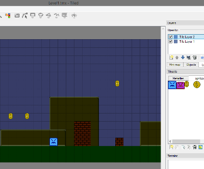
Now, I didn’t like making 1 room at a time, so I made it so you could have 1 long Tiled file, and export it to csv, and convert it to arrays with CSV2C_BIG.py.

26_Tiled

(I had it auto generate an array of pointers at the bottom, but I didn’t end up using those, so I delete them, and instead made 1 larger array of pointers, with all levels in it).

const unsigned char * const Levels_list[]={
Level1_0,Level1_1,Level1_2,Level1_3,Level1_4,Level1_5,Level1_6,Level1_7,
Level2_0,Level2_1,Level2_2,Level2_3,Level2_4,Level2_5,Level2_6,Level2_7,
Level3_0,Level3_1,Level3_2,Level3_3,Level3_4,Level3_5,Level3_6,Level3_7
};

I am using 2 kinds of enemies and 2 kinds of coins.

And then, I made a picture with all the Sprite objects on it (with transparency for background), and imported that as a separate tileset in Tiled, and added another layer, where the Sprite objects are placed. I placed the enemies on that 2nd layer (as tiles), and exported another csv file. Then I wrote another .py file “CSV2C_SP.py” to convert those into arrays.

26_Tiled2

Well, I didn’t end up using it exactly like this. It mixes the coins and the enemies, and I want them in separate arrays. So, I cut and pasted the different kinds of objects into 2 different arrays. But the .py file is helpful, and definitely sped this up.

These arrays might need to be edited slightly, like if we need coins at a different X offset from the tile grid.


Again, I made 2 kinds of enemies. The chasers now collide with walls. I was going to use the same code that the hero used, but decided it was too slow to check many objects this way, so I wrote a much simpler one.

bg_collision_fast(). This only checks 2 points instead of 4.

The chaser code isn’t very smart, they only move X and never change Y. If you put them on a platform, they would float right off it like a ghost. Maybe in the future I will edit this with improved enemy move logic, so he won’t float off a platform, but rather change directions, or fall, or something.

The other enemy is the bouncer. He just bounces up and down. He checks the floor below when falling, to stop exactly at the floor point, reusing the same code from the hero checking the floor.

bg_check_low();

The second kind of coin is just an end-of-level marker. I suppose we could have added some cool sound fx for reaching the end of the level, or an animation. That would have been nice. Currently, it just fades to black in the switch mode.

Oh, yeah. I added more modes. More game states. title, game, pause, end, switch (transition from one level to another). These are fairly obvious as how they work.

Debugging wasn’t too bad. Mostly I was worried about running past the frame and getting slowdown. I was testing code by placing gray_line() around functions. This helped me speed up things. I combined some of the enemy steps to speed them up. And I would put a gray_line() at the end of the game logic to see how far down on the screen we were. Here’s one of the tests, back when I thought I was going to use sprite zero hit and a HUD above.

full_game_debug

We don’t want to make our enemy logic too much more complex, nor put too many objects on the same screen, or we might get slow down, so we need to test as we go, and see how many enemies we can fit on a screen before it crawls to a halt. I think we can handle 7 or 8. That’s more than I need, so we’re still ok.

And finally, I put the # of coins as sprites in the top left. I didn’t put it too high up, where it might get cut off on some old TVs. 16 pixels down is fine.

Oh, almost forgot. The sprite shuffing code. Remember from the Sprite page, I mentioned that you can only have 8 sprites per horizontal line? Well, since that is a possibility, we must add some kind of shuffling to the position of each object inside the OAM buffer, so that we don’t have an enemy disappear entirely.

The simplest way to do this would be to change the starting position each frame. Instead of sprid = 0, you would do sprid = rand8() * 4, or something like that. It wouldn’t be very good, though.

I decided to go through the list of enemies in a different order each frame (and keep sprid = 0 at the top of the sprite drawing code).

const unsigned char shuffle_array[]={
0,1,2,3,4,5,6,7,8,9,10,11,12,13,14,15,
15,14,13,12,11,10,9,8,7,6,5,4,3,2,1,0,
0,2,4,6,8,10,12,14,1,3,5,7,9,11,13,15,
15,13,11,9,7,5,3,1,14,12,10,8,6,4,2,0
};

So, the first pass, it goes forward 0-15. The second pass it goes in reverse. The 3rd pass it does even then odds. The 4th pass, reverse that. This would break immediately if we changed the # of enemies, so it could use some improvement. Also, I’m not shuffling coins, so I have to make sure there aren’t too many coins on the same horizontal line.

And here’s our working game, with 3 levels, 8 rooms each. This could have been expanded a bit. It takes about 2000 bytes per level. We have about 16000 bytes left, so we could have added 7-8 more levels… so maybe 10 levels total. If we needed more than that, we would need to think about a different mapper, or maybe some kind of compression.

26_full_game2

https://github.com/nesdoug/26_Full_Game/blob/master/full_game.c

https://github.com/nesdoug/26_Full_Game


And, that’s all. Go make some games.


22. Zapper / Power Pad

$
0
0

Zapper

cof

The zapper gun came with many NES consoles. They are pretty common, but you need a CRT TV for them to work. You can also play on most emulators using the mouse to click on the screen (make sure you set the 2nd player input to “zapper”).

It is possible to play a modified game on an non-CRT TV using a Tommee brand Zapp Gun. You would need to add a 3-4 frame delay in the code, since LCD screens typically have 3-4 frames of lag. You couldn’t play the standard Duck Hunt, but some people have been working on modifying zapper games to have a delay before reading the zapper.

Ok, so we’ve all seen Duck Hunt. Do you know how it works?

DuckHunt3

The game reads the 2nd player port until it gets a signal that the trigger has been pulled. Once that happens, it blacks out the background and replaces 1 object per frame with a big white blob. If there are 2 objects on screen, it will display the first object on 1 frame and the other object on the next frame… to tell which object you hit (if any).

Duck Hunt uses 32×32 pixel box for standard ducks (4 sprites by 4 sprites). Which is about the size you want for a medium level difficulty. Other games had much bigger things to shoot and much bigger white boxes. To vary the difficulty, they would then change the amount of time that the target was on screen.

DuckHunt1

Duck Hunt used 24×16 pixel box for clay pidgeons. (3 wide by 2 high). Which is kind of difficult to hit. 24×24 is a little more reasonable, and that’s what I used.

DuckHunt2

I had to write a different controller reading routine, due to the zapper using completely different pins than the standard controllers. I threw in this zaplib.s and zablib.h files.

zap_shoot(1) takes 1 arg, (0 for port 1, 1 for port 2). And, it returns 0 or 1 if it reads the trigger has been pulled.

I also checked to make sure the last frame didn’t also have trigger pulled.

zapper_ready = pad2_zapper^1;

zapper_ready is just the opposite of the last frame. That’s a bitwise XOR, if you’re not familiar with the caret operator “^”.

So when we get that signal, I turn off the BG… ppu_mask(0x16); and draw a white box where the star was… draw_box();

0x16 is 0001 0110 in binary, see the xxxx 0xxx bit is zero. That’s the “show BG” bit. It’s off, but the sprites are still on.

Then immediately, I turn the BG back on, ppu_mask(0x1e); so the flicker is minimized.

0x1e is standard display. 0001 1110 in binary has the xxxx 1xxx bit active again.

And I call zap_read(1) takes 1 arg, (0 for port 1, 1 for port 2).

which is a loop that waits till it either gets a signal that the gun sees white, or that the end of the frame has been reached. It returns 0 for fail and 1 for success.

I tested this on a real CRT on a real NES, and it seems to work fine at 5 ft. This game uses port 2 for the zapper, which is kind of standard. But, you could make a game that uses port 1, if you wanted to. zaplib.s will have to be included in crt0.s and zaplib.h will have to be included in your main c file.

If you want the game to run on a Famicom, you should put the zapper reads on port 2. The zapper will have to be plugged into the expansion port which is read from port 2.

screenshot28

https://github.com/nesdoug/28_Zapper

Also see the wiki for more technical info.

https://wiki.nesdev.com/w/index.php/Zapper


Power Pad

PowerPad

The Power Pad is a little less standard. There weren’t many games that used it. Just like the zapper, the Power Pad uses different pins than the standard controller, so I had to rewrite the code that reads the input. See padlib.s and padlib.h.

read_powerpad(1) takes 1 arg, 0 for port 1, 1 for port 2.

And, it returns a 2 byte value (unsigned int). And I made these contants to represent each foot pad.

#define POWERPAD_4 0x8000
#define POWERPAD_2 0x4000
#define POWERPAD_3 0x2000
#define POWERPAD_1 0x1000
#define POWERPAD_12 0x0800
#define POWERPAD_5 0x0400
#define POWERPAD_8 0x0200
#define POWERPAD_9 0x0100

#define POWERPAD_6 0x0040
#define POWERPAD_10 0x0010
#define POWERPAD_11 0x0004
#define POWERPAD_7 0x0001

padlib.s will have to be included in crt0.s and padlib.h will have to be included in your main c file. This was tested on a real Power Pad on a real NES.

If you want the game to run on a Famicom, you should put the power pad reads on port 2. The power pad will have to be plugged into the expansion port which is read from port 2.

screenshot29

https://github.com/nesdoug/29_Powerpad

Also see the wiki for more technical info.

https://wiki.nesdev.com/w/index.php/Power_Pad


What is everything?

$
0
0

Someone asked me to explain all the files. Let’s try to do that. Look at the most complicated one.

https://github.com/nesdoug/26_Full_Game

in BG/

The .tmx files are from tiled map editor. Tiled uses the Metatiles.png and Sprites.png files to as its tileset, and the exported tilemaps are the .csv files. You can’t import a csv into a c project, so I wrote some python scripts to convert .csv files into .c files. Two different python files, one for background and one for sprites, so all the .c files with “SP” are sprite object lists.

All the .c files are included into the project.

in BUILD/

The .nes file is our game that can be run in an emulator.

The .s file is the assembly generated by the cc65 compiler, just in case you want to debug by looking though the ASM.

The labels.txt file is a list of all the addresses of every label in the code. You can also use this for debugging, by setting breakpoints for these addresses.

in LIB/

is all the neslib files (neslib.h and neslib.s) and all the funtions that I wrote (nesdoug.h and nesdoug.s). The .s files are included in crt0.s near the bottom. The .h files are included in the main c file.

in MUSIC/

The .ftm files are Famitracker 0.4.6 files. 1 for music and 1 for sfx. The music file was exported as a .txt file (included here) and processed with text2data (from Shiru’s famitone2 files) into TestMusic3.s. The sfx was exported as .nsf (Nintendo Sound Format) and then processed with nsf2data (also famitone2) into SoundFx.s.

famitone2.s is the famitone code (again, Shiru’s website). All the .s files are included somewhere in crt0.s. If we had DPCM samples, they would also be included in crt0.s in the “SAMPLES” segment.

in NES_ST/

The .nss files are NES Screen Tool 2.3 files. I saved one (title) as a .h compressed RLE, which the game includes and decompresses. I made a .nss file with all the kinds of block in the game (metatiles), and save to .nam (uncompressed list of the entire screen), which meta.py python script converted into a C array in metatiles.txt. Also I did a print screen from both the metatile.nss and sprite.nss files and cropped down in GIMP and save those as the .png files up in the BG/ folder (used by tiled map editor).

The other files are…

License.txt – just the MIT licence

Sprites.h – arrays of all the metasprite definitions, generated by NES Screen Tool (or by hand, which is sometimes faster)

compile.bat – to recompile the project (on Windows)

crt0.s – is all the startup code, but also a convenient place to include asm or binary files.

full_game.c – the game code. I like to use notepad++ to write my code.

full_game.chr – the graphics file, split into 2 sections, the 256 BG tiles, and the 256 Sprite tiles.

full_game.h – variables and constants and prototypes, and some constant arrays

level_data.c – lists of game data and things included for each level

nrom_32k_vert.cfg – the linker file for ld65, tells where each segment goes in the final binary.

screenshot26.png – just a picture of the game.


And some more info on compile.bat

This is a list of command line inputs for compiling the game from scratch. If you change the name of your project, change set name=full_game” to match the main code filename. Or you can change this line

cc65 -Oirs %name%.c –add-source

to

cc65 -Oirs filename.c –add-source

where filename is the name of the .c file. You can process multiple C files this way, just make sure to also use ca65 to convert each .s file into a .o object file.

-Oirs are optimizations.

–add-source tells it to put the source code in comments in the asm file.

If you have multiple object files you need to change the linker (ld65) line to list every .o file.

ld65 -C nrom_32k_vert.cfg -o %name%.nes crt0.o %name%.o nes.lib -Ln labels.txt

to

ld65 -C nrom_32k_vert.cfg -o targetname.nes crt0.o file1.o file2.o file3.o nes.lib -Ln labels.txt

-o blah tell it what to name the output file.

If you use cl65 instead of cc65/ca65/ld65, then make sure to set target = NES. It sets a strange default target, which does not use standard ASCII encoding.

del *.o deletes the object files.

move /Y labels.txt BUILD\
move /Y %name%.s BUILD\
move /Y %name%.nes BUILD\

moves these files into the BUILD folder

BUILD\%name%.nes

just runs the game, which is in the BUILD folder.


Hope this helps.


All Direction Scrolling

$
0
0

I’ve been planning to make a game that can freely scroll in all directions, like a modern game. The issue with the NES is that it only has enough VRAM for 2 nametables. So, the background is mirrored left to right (horizontal mirror) or top to bottom (vertical mirror). You could use 4 screen mirroring, but that required an extra RAM chip on the cartridge, which was an expense that almost no games used (and people seem to think this is a bit of a cheat, as it isn’t using the basic hardware).

And, when you only have 2 nametables to work with, moving in the perpendicular direction will always be visible. The oldest TVs tended to cut off as much as 8 pixels from the edges of the screen, so maybe you couldn’t see the changes. But, modern TVs and emulators can show 100% of the pixels (256 x 240). So, we want to minimize the visible changes. Including the attribute table, which only has 16×16 granularity.

Vertical Mirroring

#0 #1

#0 #1

A side scroller layout can easily hide the right and left scroll changes, just off screen. But you would see the changes at the top and bottom. Ideally you would have it only update when the Y scroll is aligned to the 8’s (08, 18, 28, 38, etc). So that 8 pixels at the top and 8 pixels at the bottom at most, which would be hidden by most old TVs. Like this.

zBlaster

Another option is to turn the screen off with carefully timed writes to the 2001 register. This would require a mapper with a scanline counter, like MMC3.

zKiwi

…here the bottom 16 pixels are hidden by turning the screen off at the bottom (with a write of zero to 2001). The bottom is the safest / easiest way to hide the visual glitches.

Or, a little more excessive, this game turns both the top 16 pixels off and the bottom 16 pixels off…

zJurass

I guess for a more balanced visual. But, not really necessary. The screen is turned off at the top of the screen, then back on at line 16 and then back off again at line 224.


Horizontal Mirroring

#0 #0

#2 #2

With horizontal mirroring, you can easily hide changes in the top and bottom just off screen, but the right and left side changes would be visible.

I’m sure you’ve played Super Mario Bros 3, and noticed the tiles change on the right side of the screen, and be the wrong color. So why would you intentionally put the changing tiles at exactly where the user is looking? Oh, well. Let’s see what other games did.

The NES does have a way of hiding the left 8 pixels of the screen in the 2001 register.

https://wiki.nesdev.com/w/index.php/PPU_registers

By resetting these bits to zero xxxx x00x the left 8 pixels will use the universal BG color (3f00) for the entire strip. Thus, you would only (ideally) 8 pixels worth of changes visible, which might be hidden on the overscan of the old TV. Here on the right…

zNemo

To be the least visible, you would change tiles every 8 X scroll movements (hidden on the left) and change attribute tables on the 8’s (08, 18, 28, 38, etc) to best hide that on the far right.

And, another interesting choice, Kirby changes tiles and attributes on the left 16 pixels, which would be the simplest for programming. And, change attribute tables on the 0’s.

zKirby

But we could go 1 step further and draw a column of black sprites along the right edge. Combined with the left 8 turned off, this is the maximum level of hiding scrolling glitches with standard hardware. If programmed right, you shouldn’t see any tiles changing nor attribute table glitches.

zFelix

…but this requires sprites to be in 8×16 mode, and steals 15 sprites from you. And, worst of all, reduces the number of usable sprites per horizontal line from 8 to 7.

I bet you thought that was enough, right, but look at this game (vertical mirroring)…

zJungle

…that cuts 16 pixels off the top and more than 16 pixels off the bottom, and has the left 8 pixels turned off. Hmm. That might be a bit excessive.


Single Screen Mirroring

A few games (AxROM) use this and attempt to do all direction scrolling. This is not recommended. Cobra Triangle minimizes the attribute table glitches by just having only 1 BG palette used for the entire play area, and then switches to another screen for the bottom area (which uses a different BG palette). The left 8 pixels are turned off to hide left to right scrolling changes, and the swapped screen at the bottom hides the top to bottom changes.

zCobra


Alternating Mirroring

Some mappers (like MMC1 and MMC3) can change between Horizontal and Vertical mirroring. Usually having sections of the game that are strictly side scrolling…

zMet1

and some sections that are strictly vertical scrolling…

zMet2

But, I don’t consider these all-direction scrolling. And it requires a special mapper.


TODO

I haven’t written the code to make my own all-direction scroller, yet. I did some test code for 4 screen mirroring and scrolling any direction, but I would prefer to rewrite it with standard 2 screen mirroring.

And I think the easiest would be to do what Kirby did, with the left 8 pixels turned off and attribute tables updated on the left on the 0’s (10, 20, 30, 40) of X scroll change. So I might attempt that first.


22. Advanced mapper MMC1

$
0
0

A mapper is some circuitry on the cartridge that allows you to “map” more than 32k of PRG ROM and/or more than 8k of CHR ROM to the NES. By dividing a larger ROM into smaller “banks” and redirecting read/writes to different banks, you can trick the NES into allowing much larger ROMs. MMC1 was the most common mapper.

MMC1 – 681 games
MMC3 – 600 games
UxROM – 270 games
NROM – 248 games
CNROM – 155 games
AxROM – 76 games
*source BootGod

NES_SLROM

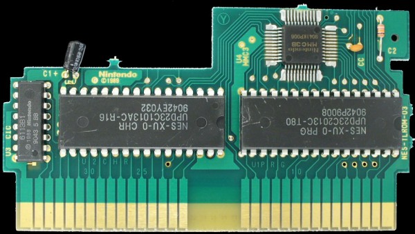
I borrowed this from Kevtris’s website. The smaller chip on the bottom left says “Nintendo MMC1A”.


MMC1 has the ability to change PRG banks and CHR banks. It can have PRG sizes up to 256k and CHR sizes up to 128k. (some rare variants could go up to 512k in PRG, but that won’t be discussed). It can change the mirroring from Horizontal to Vertical to One Screen. Metroid and Kid Icarus were MMC1, and they switch mirroring to scroll in different directions.

The MMC1 boards frequently had WRAM of 8k ($2000) bytes at $6000-7FFF, which could be battery backed to save a game. When I tried to make an NROM demo with WRAM, several emulators (and my PowerPak) decided that the WRAM didn’t exist because no NROM games ever had WRAM. But you wouldn’t have that problem with MMC1.

(In the most common arrangement…) The last PRG bank is fixed to $C000-FFFF and the $8000-BFFF can be mapped to any of the other banks. PRG banks are 16k ($4000) in size. Graphics can be swapped too. You can either change the entire pattern tables (PPU $0-1FFF) or change each separately (PPU $0-FFF and $1000-1FFF). CHR banks are 4k ($1000) in size. One thing you can do with swappable CHR banks is animate the background like Kirby’s Adventure does (by changing CHR banks every few frames).

I chose a 128k PRG ROM and 128k CHR ROM, and have it set to change each tileset separately.

Behind the scenes, the MMC1 mapper has registers at $8000,$A000,$C000, and $E000. It has to write 5 times to each, because it technically can only send 1 bit at a time. The $8000 register is the MMC1 control, the $A000 register changes the first CHR bank (tileset #0), the $C000 register changes the second CHR bank (tileset #1) (does nothing if CHR are in 8k mode), and the $E000 register changes which PRG bank is mapped to $8000-BFFF.

This is all tricky to program, in general, and more so for cc65. It is important to keep the main C code and all libraries in the fixed bank, including the init code (crt0.s) where the reset code and vectors are and neslib.s where the nmi code is. Level data should go in swapped banks. Infrequently used code should go in swapped banks.

Music is special. You would typically reserve an entire bank for music code and data. And all the music functions have to swap the music code/data in place to use it. You will need to explicitly put the music in a certain bank and change the SOUND_BANK definition to match it (in crt0.s).

Most of this new code was written by cppchriscpp with slight modification by me. Here’s the link to Chris’s code…

https://github.com/cppchriscpp/nes-starter-kit/tree/master/source


Things I changed.

I included all the files in the MMC1 folder. The .c and .h file at the top of the main .c file. The .asm files are included near the bottom of crt0.s.

In the header (crt0.s)…Flag 6 indicates the mapper # = 1 (MMC1). The NES_MAPPER symbol is defined in the .cfg file. Flags 8, indicate 1 PRG RAM (WRAM) bank. At the top of crt0.s the SOUND_BANK bank will need to be correct, and music put in the corresponding segment.

Also in crt0.s, I added the MMC1 reset code, and include the 2 .asm files in the MMC1 folder. I put the music in BANK 6, and now bank 6 is swapped before the music init code is called. All CHR files are put in the CHARS segment, which is 128k in size (it’s not completely filled).

The neslib.s file in the LIB folder has also been changed, specifically the nmi code and the music functions.

Each segment is defined in the .cfg file… MMC1_128_128.cfg. In the asm files, you just have to put a .segment “BANK4” to put everything below that in BANK 4. In the .c and .h files, you have to do this…

#pragma rodata-name (“BANK4”)
#pragma code-name (“BANK4”)

RODATA for Read Only data, like constant arrays.
CODE for code, of course.

Look at the ROM in a hex editor, and you can see how the linker constructed the ROM. I specifically wrote strings called “BANK0” in bank #0 and “BANK1” in bank #1, etc.

HexView

What’s new?

Banked calls are necessary, when calling a function in another bank.

banked_call(unsigned char bankId, void (*method)(void));

What this does is push the current PRG bank on an array, swap a new one in place, call the function with a function pointer, return, and pop the old bank back into place, then return. You can even nest banked_calls from one swapped bank to another, but there is a limit of 10 deep before it breaks. In fact, these banked_calls are very slow, so try to stay in one bank as much as possible before switching.

Also, music functions are in their own bank, and it has to do a similar…save bank, swap new one, jump there, return, pop bank, return… thing for any music or sfx call. So, try to minimize how many sfx you call in a frame.

set_prg_bank(unsigned char bank_id);

Use this to read data from a swappable bank (from the fixed bank). It sets a specific bank at $8000, and then you can access the data there.

set_chr_bank_0(unsigned char bank_id);
set_chr_bank_1(unsigned char bank_id);

Use these to change the CHR banks. bank_0 for the first set (which I used for background). bank_1 for the second set (which I used for sprites).

set_mirroring() to change the mirroring from Horizontal to Vertical to Single Screen.

If you are doing a split screen, like with a sprite zero hit, you could set the CHR bank that shows at the top of the screen with this function.

set_nmi_chr_tile_bank()

And turn it off with this function.

unset_nmi_chr_tile_bank()


Look at the code…

in main(), it uses

banked_call(BANK_0, function_bank0);

This function swaps bank #0 into place, then calls function_bank0(), which prints some text, “BANK0”, on the screen.

banked_call(BANK_1, function_bank1);

Does the same, but if you look at function_bank1(), it also calls

banked_call(BANK_2, function_bank2);

to show that you can nest one banked call inside another…up to 10 deep.

And we see that both “BANK1” and “BANK2” printed, so both of those worked.

Next we see that this banked_call() can’t take any extra arguments, so
you would have to pass arguments with global variables…I called them arg1 and arg2.

arg1 = ‘G’; // must pass arguments with globals
arg2 = ‘4’;
banked_call(BANK_3, function_bank3);

function_bank3() prints “BANK3” and “G4”, so we know that worked. Passing arguments by global is error prone, so be careful.

Skipping to banked_call(BANK_5, function_bank5);

function_bank5() also calls function_2_bank5() which is also in the same bank. You would use standard function calls for that, and not banked_call(). It printed “BANK5” and “ALSO THIS” so we know it worked alright. Use regular functions if it’s in the same bank.

Finally, banked_call(BANK_6, function_bank6); reads 2 bytes from the WRAM at $6000-7FFF. Just to have an example of it working. In the .cfg file I stated that there is a BSS segment there called XRAM. At the top of this .c file I declared a large array wram_array[] of 0x2000 bytes. You can read and write to it as needed.

It printed “BANK6” and “AC” (our test values) correctly.

Once we return to the main() function, we know we are in the fixed bank. Without using banked_call() we could swap a bank in place using set_prg_bank(). We could do that to read data in bank… like, for example, level data. You just read from it normally, as if that bank was always there.

I recommend you never use set_prg_bank() and then jumping to it without using banked_call(). The bank isn’t saved to the internal bank variable. If an NMI is triggered, the nmi code swaps the music code in place and then uses the internal bank variable to reset the swapped bank before returning… and that would be the wrong bank, and it would crash. Actually, this scenario might work without crashing. But I still recommend using the banked_call().

There is an infinite loop next, that reads the controller, and processes each button press.

Start button = changes the CHR bank. It calls this function…

set_chr_bank_0(char_state);

Which changes the background tileset. You notice that the sprite (the round guy) never changes. Sprites are using the second tileset. If we wanted to change the second tileset, we would use…

set_chr_bank_1();

MMC1_A

MMC1_B

MMC1_C

I am also testing the music code. Start calls a DMC sample. Button A calls the song play function music_play(). Button B calls a sound effect sfx_play(). and Select pauses and unpauses the music with music_pause().

I just wanted to make sure that the music code is working correctly, because I rewrote the function code. All the music data and code is in bank #6, and the code swaps in bank #6 and then calls the music function. Then swaps banks back again before returning.

I didn’t show any examples of changing the mirroring, but that is possible too.


Link to the code…

https://github.com/nesdoug/32_MMC1


I’m glad I got this working. Now on to actual game code. Oh, also… I was using MMC1_128_128.cfg but you could double the PRG ROM to 256k, by using the MMC1_256_128.cfg (edit the compile.bat linker command line arguments).

You could easily turn the WRAM at $6000-7FFF into save RAM by editing the header. Flags 6, indicate contains battery-backed SRAM, set bit 1… so add 2 to flags 6 in the header in crt0.s.

Maybe next time I will make an MMC3 demo, which can easily use 512k PRG ROM and 256k CHR ROM, and has a scanline counter. Also, there is a homebrew mapper 30, the oversized UNROM 512 board with extra CHR-RAM and (optional) 4-screen mirroring. Either would be easy to adapt the banked call system.

Review – 150 Classic NES Games for GBA

$
0
0

Review – 150 Classic NES Games for GBA

I bought this cart for about $20 US from some store on Amazon. It uses the PocketNES emulator to run NES games on a Gameboy Advanced.

20191009_162639

Here is a list of games on it…

Adventure Island 1, 2, 3, & 4,
Adventures of Lolo 1, 2 & 3,
Astyanax,
Batman,
Battletoads,
Battletoads & Double Dragon
Bionic Commando,
Blades of Steel,
Blaster Master,
Bomberman 1 & 2,
A Boy and His Blob,
Bubble Bobble 1 & 2,
Castlevania 1, 2 & 3,
Chip n Dale Rescue Rangers,
Cobra Triangle,
Contra,
Contra Force,
Crystalis,
Devil World,
Donkey Kong,
Donkey Kong Jr.,
Double Dragon 1, 2 & 3,
Dr. Mario,
Dragon Warrior 1, 2, 3 & 4,
Duck Tales,
Excitebike,
Faxanadu,
Fester’s Quest,
Final Fantasy 1, 2 & 3,
Fire ‘n Ice,
Galaga,
Ganbare Goemon,
Gargoyles Quest 2,
Ghostbusters,
Ghosts ‘n Goblins,
Goonies 2,
Gradius,
Guardian Legend,
Gun Nac,
Holy Diver,
Ice Climber,
Ice Hockey,
Ikari Warriors,
Jackal,
Journey to Silius,
Kickle Cubicle,
Kid Icarus,
Kid Niki,
Kirby’s Adventure,
Klax,
Kung Fu,
Legend of Zelda 1, & 2,
Legend of Zelda Outlands,
Legendary Wings,
Lemmings,
Lifeforce,
Little Nemo,
Little Samson,
Lode Runner,
Maniac Mansion,
Marble Madness,
Mario Bros.,
Mario Open Golf,
Mega Man 1 thru 6,
Metal Gear,
Metroid,
Mickey Mousecapade,
Micro Machines,
Moon Crystal,
Mother,
Mr. Gimmick,
Ms. Pac-Man,
New Ghostbusters II,
Ninja Gaiden 1, 2 & 3,
Over Horizon,
Pac-Man,
Paperboy,
Parasol Stars,
Parodius,
Pipe Dream,
Power Blade,
Prince of Persia,
Qix,
Rad Racer,
RC Pro-Am,
Ring King,
River City Ransom,
Rush’n Attack, Rygar,
Section Z,
Shadowgate,
Shatterhand,
Skate or Die 2,
Snake Rattle n Roll,
Snake’s Revenge,
Solomon’s Key,
Solstice,
Space Invaders,
Star Force,
Star Soldier,
Star Tropics 1 & 2,
Summer Carnival ’92,
Super C,
Super Mario Bros. 1, 2 (USA & Japan) & 3,
Sweet Home,
Tecmo Super Bowl,
Tetris,
TMNT 1, 2 & 3,
To The Eartch,
Twinbee 1, 2 & 3,
Ufouria,
Vice Project Doom,
Wario’s Woods,
Willow,
Wizards & Warriors,
Xevious,
Yoshi’s Cookie,
Zanac

However, Cobra Triangle immediately crashes when the game starts. Klax has glitched graphics. And To The Earth is a zapper game, and PocketNES has no zapper support, so it is also unplayable. 147 playable, out of 150. Here’s Klax…

20191031_142555

Some of the games have very minor glitches, usually on the title screen. The other games seem to play ok. The first thing I noticed was that the games are a bit dark and some games with tiny bullets are hard to see. This is with max brightness…

20191031_142415

I believe the GBA SP has an internal light source, which would help. I suppose I’m too used to new cell phones, which have very bright screens.

There are several display options…

20191031_143306

Scaled BG and Obj (squashed)

20191031_143145


Unscaled, you can’t see the whole screen, but L and R buttons shift the screen up and down… which is kind of a pain.

20191031_143222


Unscaled Follow. Same as above, but the screen tries to snap to the main character. You still can’t see the floor below.

20191031_143248


I think the Scaled version is the most playable, even if everything is squashed. It cuts a few pixels off the top and bottom, so you can’t really see the ENTIRE screen.


Press L + R to get the menu, A to choose, B to cancel.

20191031_144733

You can do save states, which really sells this game for me. Not having to replay the entire game every time you play is a huge benefit.

Exit takes you to the start of the game selection menu, with selection at the first game. Restart also takes you to the game selection menu, but selection is at the last game played.

Some games auto save the SRAM. Games like Dragon Warrior. However, there isn’t enough memory on the cartridge to save all 150 games. At some point when I was scrolling through the games it gave me a weird error message of memory full and I was required to delete one of the in-game saves.

The music / sound quality is good. The game selection is good. I wish it had Mike Tyson’s Punch-Out!! but PocketNES can’t emulate it correctly, so they left it out. I read that Castlevania 3 isn’t fully emulated, but it seems to play ok. I don’t see any problems.

Here’s some more options.

20191031_143452

Somewhere I read that you should keep Autosave OFF or something bad will happen.

However, you can do this for savestates…

Quick load: R+START loads the last savestate of the current rom.
Quick save: R+SELECT saves to the last savestate of the current rom


Another thing you can do is speed up and slow down the game…

Speed modes: L+START switches between throttled/unthrottled/slomo mode

But, speed up is TOO FAST and slomo is TOO SLOW. I don’t find this feature useful.


Overall Review = A-

Not perfect, but definitely worth the $20.


23. Advanced Mapper – MMC3

$
0
0

MMC3 is the 2nd most popular mapper. Many of the most popular games were MMC3. Several of the Megaman games. Super Mario Bros 2 + 3. This photo is borrowed from bootgod. The little chip at the top says MMC3B.

Megaman3

MMC3 PRG banks are $2000 in size. Max size is 512k (64 of those PRG banks).

MMC3 CHR banks are $400 in size. Max size is 256k (256 of those CHR banks). This extra small size makes it possible to change 1/4 of a tileset.

Although, only one of the tilesets can do this. The other can only change 1/2 at a time. Which one is optional, but I would prefer the BG to have the smaller banks, so that it more easily animate the backgroud without wasting too much memory.

MMC3 can have WRAM, some times with a battery for saving the game.

MMC3 can change between Horizontal and Vertical mirroring, freely.

Best of all. MMC3 has a scanline counter hardware IRQ. That means you can very exactly time mid-frame changes, such as scrolling changes. You can do parallax scrolling, like the train stage on Ninja Gaiden 2.

Since IRQ code needs to be programmed in Assembly, instead of having you, the casual C user, try to write your own… I made an automated system, that can do most anything you would need it to do mid-screen. (I will discuss a little later)

I don’t want to get into all the details of how the hardware works, which you can find here, if you want to read them.

https://wiki.nesdev.com/w/index.php/MMC3

There are multiple screen splits (timed by IRQ) and I’m animating the gears by swapping CHR banks. Also, the music is in a swappable bank.
Let’s go over every thing that had to be changed…

MMC3_128_128.cfg

I made several $2000 byte swappable banks. The C code and all the libraries need to go in a fixed bank. I decided to keep $a000-ffff fixed to the last 3 banks. That means all the swappable banks will go in the $8000 slot… which is why we have all those banks start at $8000. Technically, MMC3 has the ability to swap the $a000-bfff bank, but I’m adapting the code from the MMC1 example, which only expects 1 swappable region, so let’s pretend that you can’t change $a000.

The startup code (reset code) needs to be in the very last $e000-ffff area, because this is the only bank that, by default, we know the position of. Vectors also go here.

Again, this mapper can have WRAM at $6000, so I made that segment to test it. You would need to change the BSS name to XRAM (what I called this segment) to declare a variable or array here.

In the Assembly code, just inserting a .segment like .segment “CODE” makes everything below that point map into that bank.

In the C code, you need to use a pragma, like
#pragma bss-name(push, “ZEROPAGE”)
#pragma bss-name(pop)

or

#pragma rodata-name (“BANK0”)
#pragma code-name (“BANK0”)

to direct the various types of things into the correct bank.

At the bottom of MMC3_128_128.cfg, it defines some symbols, NES_MAPPER=4.
And size of each ROM chip (NES_PRG_BANKS=8). MMC3 can be expanded to  512k PRG and 256k CHR, if you need.


crt0.s

This is the reset code and where most .s files are included. For example, mmc3_code.asm is included here. All in the “STARTUP” segment, so we know it is mapped to $e000-ffff, the default fixed bank.

I inserted a basic MMC3 initialization, which puts all the banks in place (and bank 0 into the $8000 slot). It also, importantly, does a CLI to allow IRQs to work on the CPU chip.

Also, I defined “SOUND_BANK 12”, and put the music data there, in BANK 12. All the music code will swap that bank in place, to play songs.


MMC3 folder

mmc3_code.asm

is all the hidden code that you shouldn’t have to worry about. Except if you want to change the A12_INVERT from $80 to 0. This determines which tileset will get the smaller bank $400 size and which will get the larger $800. I have it $80 so that background has the smaller tile banks, so that swapping BG CHR banks (to animate the background) uses less space.

If you prefer to have smaller sprite banks, change this number to 0. This also changes which CHR bank mode you need to change BG vs sprite tiles.

;if invert bit is 0
;mode 0 changes $0000-$07FF
;mode 1 changes $0800-$0FFF

;mode 2 changes $1000-$13FF
;mode 3 changes $1400-$17FF
;mode 4 changes $1800-$1BFF
;mode 5 changes $1C00-$1FFF

;if invert bit is $80
;mode 0 changes $1000-$17FF
;mode 1 changes $1800-$1FFF

;mode 2 changes $0000-$03FF
;mode 3 changes $0400-$07FF
;mode 4 changes $0800-$0BFF
;mode 5 changes $0C00-$0FFF

mmc3_code.c

is the bank swapping code. This is the same as the MMC1 example.
You only need the banked_call() function. Anytime you call a function that is in a swappable bank, you use..

banked_call(unsigned char bankId, void (*method)(void))

(which bank is it in, the name of the function)
Don’t nest more than 10 function calls deep this way, or it will crash.

mmc3_code.h

Here is the new stuff that you need to know.

set_prg_8000(unsigned char bank_id);

this changes which bank is mapped to $8000. I prefer that you use the banked_call() function, which automatically does this for you. You could use this to read data from a certain bank.

get_prg_8000()

returns the number of the bank at $8000

set_prg_a000()

don’t use this, for how I have it set up. It would change the bank mapped at $a000. Currently, we have code mapped here, which could crash if it was missing.

set_chr_mode_0(unsigned char chr_id);
set_chr_mode_1(unsigned char chr_id);
set_chr_mode_2(unsigned char chr_id);
set_chr_mode_3(unsigned char chr_id);
set_chr_mode_4(unsigned char chr_id);
set_chr_mode_5(unsigned char chr_id);

these change which parts of the CHR ROM are mapped to the tilesets.
See the chart above.

set_mirroring(unsigned char mirroring)

to change the PPU mirroring layout. Horizontal or Vertical.

set_wram_mode()

this could turn the WRAM on and off. I turned it ON by default.

disable_irq()

turns off the irq, and redirects the IRQ SYSTEM to point to 0xff (end).

et_irq_ptr(char * address)

turns on the IRQ SYSTEM, and points it to a char array.


IRQ SYSTEM

So I should talk about this IRQ stuff. An IRQ is a hardware interrupt.
The MMC3 has a scanline counter. Once it is set, it counts down each line that is drawn. When it reaches zero, it jumps to the IRQ code. The standard use for the scanline IRQ is to make mid-screen scrolling changes, such as parallax scrolling.

The IRQ code would need to be written in Assembly. Instead of expecting you to learn this to make it work, I wrote an automated system that will parse a set of instructions (char array) and execute the necessary code behind the scenes. Here’s how it works.

A value < 0xf0, it’s a scanline count
zero is valid, it triggers an IRQ at the end of the current line

if >= 0xf0…
f0 = 2000 write, next byte is write value
f1 = 2001 write, next byte is write value
f2-f4 unused – future TODO ?
f5 = 2005 write, next byte is H Scroll value
f6 = 2006 write, next 2 bytes are write values

f7 = change CHR mode 0, next byte is write value
f8 = change CHR mode 1, next byte is write value
f9 = change CHR mode 2, next byte is write value
fa = change CHR mode 3, next byte is write value
fb = change CHR mode 4, next byte is write value
fc = change CHR mode 5, next byte is write value

fd = very short wait, no following byte
fe = short wait, next byte is quick loop value
(for fine tuning timing of things)

ff = end of data set
Once it sees a scanline value or an 0xff, it exits the parser.
Small example…
irq_array[0] = 47; // wait 48 lines

irq_array[1] = 0xf5; // 2005, H scroll change
irq_array[2] = 0; // change it to zero
irq_array[3] = 0xff; // end of data

This will cause it to, at the very top of the screen, set the scanline counter for 47. The screen will draw the top 48 lines (it’s usually 1 more than the number) then an IRQ will fire.

It will read the next lines, and change the Horizontal scroll to zero, then it will see the 0xff, and exit.

If it saw another scanline value (any # < 0xf0) it would instead set another scanline counter. And so on. Let’s look at the example.

MMC3_1

There are 4 IRQ splits here (red lines). I’m doing quite a lot here. This is sort of an extreme example. Let’s go over the array, and see all what’s going on.

MMC3_2

Anything put BEFORE the first scanline count will happen in v-blank,  and affect the entire screen.

irq_array[0] = 0xfc; // CHR mode 5, change the 0xc00-0xfff tiles
irq_array[1] = 8; // top of the screen, static value
irq_array[2] = 47; // value < 0xf0 = scanline count, 1 less than #

0xfc, change some tiles, mode 5, use CHR bank 8. Every frame this will always be 8 at the top of the screen. If you look at the video or the ROM, you see the top gear is not spinning. I did this on purpose to show the tile change mid-screen better.

It sees the 47, which is less than 0xf0, so it sets the scanline counter and exits.

At line 48 of the screen, an IRQ fires, the IRQ parser reads the next command.

irq_array[3] = 0xf5; // H scroll change, do first for timing
temp = scroll2 >> 8;
irq_array[4] = temp; // scroll value
irq_array[5] = 0xfc; // CHR mode 5, change the 0xc00-0xfff tiles
irq_array[6] = 8 + char_state; // value = 8,9,10,or 11
irq_array[7] = 29; // scanline count

First, it changes the Horizontal scroll. This code actually takes up an entire scanline, to try to time it near the end of a scanline so it’s not so visible. Note, you can’t change the Vertical scroll this way, only the Horizontal.

Then, it changes the background tiles, and cycles them through 4 options. This causes the gear to spin. The entire screen below this point is affected.

Then, it sets another scanline count and exits. 30 scanlines later another IRQ fires. It then reads this…

irq_array[8] = 0xf5; // H scroll change
temp = scroll3 >> 8;
irq_array[9] = temp; // scroll value
irq_array[10] = 0xf1; // $2001 test changing color emphasis
irq_array[11] = 0xfe; // value COL_EMP_DARK 0xe0 + 0x1e
irq_array[12] = 30; // scanline count

We change the H scroll again. Just to show what ELSE we can do, it’s writing a value to the $2001 register, setting all the color emphasis bits, which darkens the screen. If you move the sprite guy down, you see that he is also affected.

Another scanline count is set, for 30. It takes 31 lines, probably.
irq_array[16] = 0xf5; // H scroll change
irq_array[17] = 0; // to zero, to set the fine X scroll
irq_array[18] = 0xf6; // 2 writes to 2006 shifts screen
irq_array[19] = 0x20; // need 2 values…
irq_array[20] = 0x00; // PPU address $2000 = top of screen
irq_array[21] = 0xff; // end of data

And just to be fancy, I’m showing an example of using the $2006 PPU register mid-screen. But, to make it work, I also needed to set the $2005 register to zero with the 0xf5 command. The 0xf6 command is the only one that is expecting 2 values after it. High byte, then Low byte, of a PPU address.

Writing to $2006 mid-frame causes the scroll to realign to that address. In this example, the address $2000 is the top of the nametable, which means that the top of the nametable is drawn AGAIN, below that point.

Instead of seeing a value < 0xf0, it sees an 0xff, and exits without setting another scanline count. The parser does nothing until the top of the next line.

It would probably be a good idea to edit the IRQ Array at a time that you are certain that no IRQs will be firing, such as the very first thing in the frame. Or, I suppose, you could maintain 2 arrays, and activate one, and edit the other. Alternating each frame. But, if you were editing values at the exact spot the IRQ was reading, it could read a half written command, and interpret it incorrectly.

This example completes the list around the 5-10th scanlines, which is well before the first IRQ happens.


Swappable PRG banks

These work the same as the MMC1 code, except that the bank size is $2000.

To make the code / data go in BANK 0, use these directives

#pragma rodata-name (“BANK0”)
#pragma code-name (“BANK0”)

The function_bank0() function is compiled into bank 0. To call it, we use

banked_call(0, function_bank0);

0 is the bank, function_bank0 is the name of the function.

This jumps to banked_call(), which is in the fixed bank, it automatically swaps bank 0 in place, and then jumps to function_bank0() with a function pointer. Then it swaps the previous bank back in place, and returns.

As you see, this means that I can’t pass arguments to function_bank0().
So, we have to pass arguments via global variables. arg1, arg2, for example. Obviously, this isn’t safe practice. You could immediately pass those values to static local variables, to avoid errors.

If you call a function in the SAME swapped bank that you are already in, you can safely use regular function calls.

You can call a function from one swapped bank to another swapped bank. But, don’t keep going from one to another swapped bank too much, not more than 10 deep.

Other important notes.

For the IRQ scanline counter to work, background must use tilset #0 (which is the default)and sprites must use tileset #1 bank_spr(1). And, the screen must be on. ppu_on_all().

Here’s the link to the example code.

https://github.com/nesdoug/33_MMC3
Future plans… maybe some time, I will make a UxROM (perhaps UNROM 512) code example. This would require VRAM, which would involve compression. Otherwise, the PRG works the same as the MMC1, which we already have working example code, so it wouldn’t be too difficult to convert.

SNES Projects

$
0
0

North to the Future. The next big thing is SNESdev.

But the tools I have become used to don’t exist… so I am making my own. In place of NES screen tool, I have made 2 similar apps for the SNES.

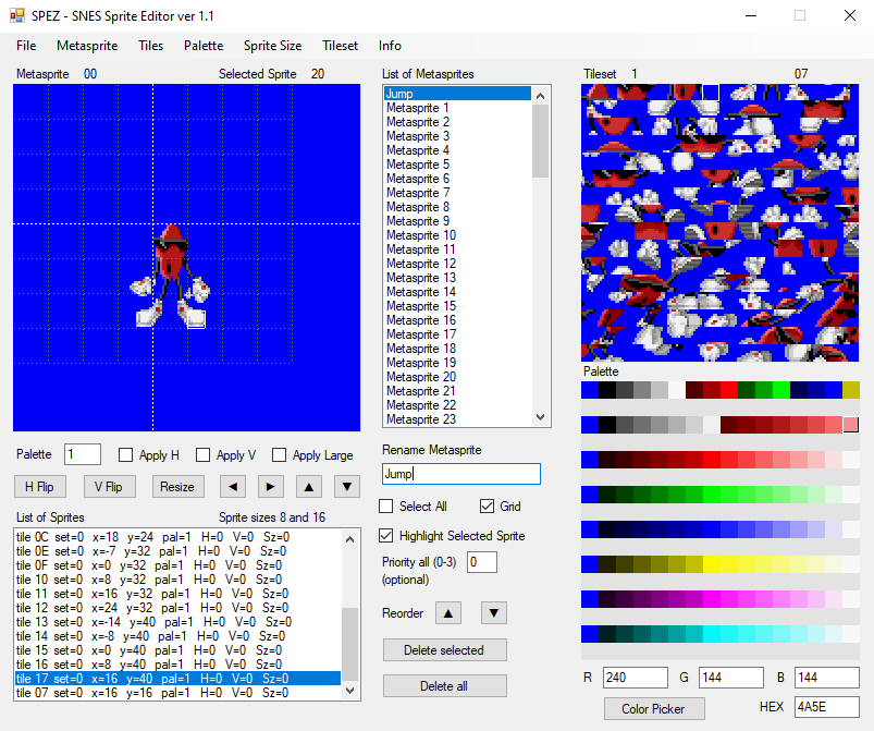
M1TE (mode 1 tile editor) for backgrounds and SPEZ for sprites.

M1TE


SPEZ

And instead of neslib for cc65, I have made easySNES library for ca65 (assembly only).

See all these projects here…

https://github.com/nesdoug/M1TE2

https://github.com/nesdoug/SPEZ

https://github.com/nesdoug/SNES_00

(example code with easySNES)

Other projects that are worth looking into… Optiroc.

https://github.com/Optiroc/SuperFamiconv

(converts images to SNES tile and map and palette format)

https://github.com/Optiroc/libSFX

(another SNES development library)

https://github.com/SourMesen/Mesen-S

(the ultimate debugging SNES emulator)


Documentation

https://wiki.superfamicom.org/

https://problemkaputt.de/fullsnes.htm


My projects will likely improve over time, so keep an eye out for updates.

I plan to write some examples, and eventually make an SNES homebrew game. Stay tuned.


.


SNES Overview

$
0
0

SNESconsole

The Super Nintendo first came out in 1991 (1990 in Japan as the Super Famicom). It was one of the best game consoles of all time, with an amazing library of games. It definitely has a special place in my heart. Before we get to programming for it, let’s take a look and see what’s under the hood.

It contains a 65816 clone chip called the Ricoh 5A22 (3.58 MHz), which is a direct descendant of the 6502 chip that powers the original Nintendo. They call it a super-set because essentially all the 6502 codes work the same on both chips. The chip has both 8 bit and 16 bit modes, and has a full 24 bit addressing space (0 to 0xFFFFFF).

(borrowed this image from https://copetti.org/projects/consoles/super-nintendo/ )

motherboard_marked

It has 128kB internal WRAM.

This unit has 2 PPU chips. Later models had 1 chip (marked as “1chip”) and are slightly better, but both function the same, other than picture quality. The PPU is what generates the video image. It has its own 64 kB of VRAM (arranged as 32 kB addresses of 16 bits). The VRAM holds our graphics and background maps.

Background tiles can be 8×8 or 16×16. Background maps can be 32×32 up to 64×64 (multiplied by the tile size). Giving from 256×256 pixel map to 1024×1024 sized map. Scrolling games will typically change the map, a column or row at a time, as you move through the level.

There is also a memory chip for color palettes (CGRAM) of 512 bytes, and a memory chip for sprite attributes (OAM) of 544 bytes, arranged as a low table of 512 and a high table of 32. Color palettes are 15 bits per color RBG 0bbbbbgggggrrrrr, so 512 bytes gives us a total of 256 colors.

Sprites are 4 bytes (and 2 extra bits) each, so 512 byte / 4 gives us 128 sprites displayable at once. Sprites can be various sizes, from 8×8 to 64×64. Typically they would be 8×8 or 16×16.

The CIC is the security chip. Each cartridge will need a matching chip to run.

The cartridge itself could contain battery backed SRAM for saving games.

On the other side of the motherboard are the audio chips. Together they are called S-SMP. And it is a system that runs independently from the CPU. It has it’s own processor, the SPC700. It has it’s own 64 kB of RAM where you load the audio program, the song data, and the audio samples.

The audio program will then process the song and set the 8 channels (DSP, digital signal processor) to play the different audio samples at different rates to generate different tones. The samples are compressed in a format called BRR.

When the SNES is switched on, the main program will have to load everything to the audio ram. This is actually a very slow process, and if you notice that games show a black screen for a few seconds when the game is first run, it is probably due to loading the sound RAM. Once the audio program is loaded, it will run automatically. The audio program can also get signals from the game (for example, to change songs, or to play a sound effect).


Graphics Modes

If you are familiar with the original Nintendo, the Super Nintendo works very similar except that everything is changeable. Backgrounds can have small tiles, large tiles, small maps, large maps, 1 layer, 2 layers, 3 layers, 4 layers, all moving independently.

You can rearrange the VRAM any way you want. You can put maps first then BG tiles then sprite tiles. Or, BG tiles first then sprite tiles then BG maps. Or, you can have one giant 256 color BG that fills the entire VRAM and no sprite tiles. Any way you want.

Here’s a quick look at the different background modes.

Mode 0

4 layers of 4 colors per tile.

This mode is not as colorful. I generally only see it used for screens of text. The main advantages are the extra layer, and the graphics files are half the usual size. This mode is the most like the original Nintendo (or maybe Gameboy Color), and a game ported from there to the Super Nintendo (with no improvements) might use mode 0.

Mode 1

2 layers of 16 colors per tile.

1 layer of 4 colors per tile.

This is the most used mode. Nearly every game uses mode 1 most of the time. Typically, the first 16 color layer for foreground and other for background. Then the 4 color layer is used for text boxes or HUD / score display.

SMW

Mode 2

2 layers of 16 color. Each tile can be shifted. See Tetris Attack, how the play area scrolls upward. This mode is very rarely used. Yoshi’s Island uses it for 1 level (Touch Fuzzy Get Dizzy).

TetrisAttack

Mode 3

1 layer of 256 colors

1 layer of 16 colors

This mode is very colorful, but the graphics files are twice as big as usual, so games typically only used them (if at all) for title screens. Like this…

Aero the Acro-Bat (USA)_000

Mode 4

1 layer of 256 colors

1 layer of 4 colors

Similar to mode 2, tiles can be shifted. Rarely used mode.

Mode 5

1 layer of 16 colors

1 layer of 4 colors

This mode can do pseudo high resolution. It is rarely used. RPM Racing uses it.

RPMracing

Mode 6

1 layer of 16 color

Also pseudo high resolution. Also can shift tiles like mode 2 or 4. I’ve never seen this used outside of demos.

Mode 7

This is the mode that really set Super Nintendo apart from other consoles. This mode is one layer that can zoom in and out and rotate the background. This mode is completely different from the other modes and has it’s own special graphics format that is hard to explain. There is one big tilemap of 128×128, 1 layer of 256 colors.

Fzero

Interestingly, mode 7 does not naturally do perspective. It can stretch and rotate only. But, games like F-zero change the stretching parameters line by line to simulate perspective. As the PPU generates the image sent to the TV, it renders each horizontal line, one at a time, and the BG image is zoomed in.

Really, all the modes can change parameters line by line. One fairly common technique is to change the main background color to create a gradient effect. It uses HDMA to do this, which is the only way to send data to the VRAM (or in this case, CGRAM) during the active screen time.

Batman

Sprites

For all the modes, the way sprites work is always the same. Sprites are always 15 colors (the 0th color always transparent). Also, sprites have different size modes (8×8, 16×16, 32×32, 64×64), and different priorities (which work like layers). You can flip them horizontally or vertically.

Like the NES, there is a limit of how many sprites can be displayed on each horizontal line, and the calculus for that it a bit complicated. If you split each large sprite into 8×1 slices, you can only fit 32 on a horizontal line. Generally this isn’t a problem, but you should be aware of it.

All the characters on the screen are sprites. Mario. Koopas. Etc. Because sprites can be large and you can fill the screen with them, and move them around easily, sprites can be used for background elements and be considered as another background layer. Title screens often have the title written in sprites, for example. And, mode 7 games use sprites as a second layer.


Other possibilities

You can change modes and settings mid screen.

You can change scrolling mid screen, and create a shifting sine wave pattern, perhaps for fire or underwater scene.

You can do color transparencies. One layer added to another (or subtracted from another).

You can use “windows” to cut a hole in the screen, or narrow the screen from the sides, or even adjust the windows line by line with HDMA and draw shapes on the screen.

All these effects are more advanced, and we shouldn’t worry too much about that stuff yet.

I plan to write some basic tutorials for getting a very simple game working on the Super Nintendo. But, we need to take it very slowly.


.


65816 Basics

$
0
0

Programming the SNES in assembly, using the ca65 assembler.

Assembly Language Basics

When computer code is compiled, in a higher level language, it is converted to a binary code (machine code) that the CPU can read and run. Binary code is very hard to read and write. So, they developed a system of mnemonics to make it easier to understand, called assembly language.

There are many different assembly languages, each targeting a specific CPU. We are targeting the 65816 (65c816) which is a more advanced version of the popular 6502 chip. The best way to learn 65816 assembly is to first learn 6502. But first, lets review the basics.

Number Systems

Binary. Under the hood, all computers process binary numbers. A series of 1s and 0s. In the binary system, each column is 2x the value of the number to the right.

0001 = 1
0010 = 2
0100 = 4
1000 = 8

You then add all the 1’s up

0011 = 2+1 = 3
0101 = 4+1 = 5
0111 = 4+2+1 = 7
1111 = 8+4+2+1 = 15

Each of these digits is called a bit. Typically, there are 8 bits in a byte. So you can have numbers from
0000 0000 = 0
to
1111 1111 = 255

Since it is difficult to read binary, we will use hexadecimal instead. Hexadecimal is a base 16 numbering system. Every digit is 16x the number to the right. We use the normal numbers from 0-9 and then letters A-F for the values 10,11,12,13,14,15. In many assembly languages, we use $ to indicate hex numbers.

$0 = 0
$1 = 1
$2 = 2
$3 = 3
$4 = 4
$5 = 5
$6 = 6
$7 = 7
$8 = 8
$9 = 9
$A = 10
$B = 11
$C = 12
$D = 13
$E = 14
$F = 15

$F is the same as binary 1111.

The next column of numbers is multiples of 16.

$00 = 16*0 = 0 _____ $80 = 16*8 = 128
$10 = 16*1 = 16 _____ $90 = 16*9 = 144
$20 = 16*2 = 32 ____ $A0 = 16*10 = 160
$30 = 16*3 = 48 ____ $B0 = 16*11 = 176
$40 = 16*4 = 64 ____ $C0 = 16*12 = 192
$50 = 16*5 = 80 ____ $D0 = 16*13 = 208
$60 = 16*6 = 96 ____ $E0 = 16*14 = 224
$70 = 16*7 = 112 ____ $F0 = 16*15 = 240

$F0 is the same as binary 1111 0000.
add that to $0F (0000 1111) to get
$FF = 1111 1111

So you see, you can represent 8 bit binary numbers with 2 hex digits. From $00 to $FF (0 – 255).

To get the assembler to output the value 100 you could write…

.byte 100

or

.byte $64

16 bit numbers

Typically (on retro systems) you use 16 bit numbers for memory addresses. Memory addresses are locations where pieces of information can be stored and read later. So, you could write a byte of data to address $1000, and later read from $1000 to get that data.

The registers on the SNES can be set to either 8 bit or 16 bit modes. 16 bit mode means it can move information 16 bits at a time, and process the information 16 bits at a time. 16 bit registers means that it will read a byte from an address, and another from the address+1. Same with writing 16 bits. It will write (low order byte) to the address and (high order byte) to address+1.

In binary, a 16 bit value can go from
0000 0000 0000 0000 = 0
to
1111 1111 1111 1111 = 65535

In hex values, that’s $0000 to $FFFF.

Let’s say we have the value $1234. The 12 is the most significant byte (MSB), and the 34 is the least significant byte (LSB). To calculate it’s value by hand we can multiply each column by multiples of 16.

$1234
4 x 1 = 4
3 x 16 = 48
2 x 256 = 512
1 x 4096 = 4096
4096 + 512 + 48 + 4 = 4660

To output a 16 bit value $ABCD, you could write

.word $ABCD
(outputs $cd then $ab, little endian style)

Don’t forget the $.

We can also get the upper byte byte or lower byte of a 16 bit value using the < and > symbols before the value.

Let’s say label List2 is at address $1234

.byte >List2
will output a $12 (the MSB)

.byte <List2
will output a $34 (the LSB).

24 bit numbers

We can now access addresses beyond $ffff. There is a byte above that called the “bank byte”. Using long 24 bit addressing modes or changing the data bank register, we can access values in that bank using regular 16 bit addressing. Here is an example of a 24 bit operation.

LDA f:$7F0000
will get a byte from address $0000 of the $7F bank (part of the WRAM).

JMP $018000
will jump to address $8000 in bank $01.

In ca65, the f: is to force 24 bit values from the symbol / label. The assembler will calculate the correct values. (to force 16 bit you use a: and to force 8 bit you use z:)

To output a 24 bit value
.faraddr $123456
(outputs $56…$34…$12)

To output the lower 16 bits of a 24 bit value, use this pseudo function
.word .loword ($123456)
(outputs $56…$34)

To output the upper 8 bits of a 24 bit value, use this pseudo function
.byte .bankbyte ($123456)
(outputs $12)

Or you could do this, to output a byte at a time.
.byte ^$123456
(outputs $12)
.byte >$123456
(outputs $34)
.byte <$123456
(outputs $56)

But we don’t want to write our program entirely using byte statements. That would be crazy. We will use assembly language, and the assembler will convert our three letter mnemonics into bytes for us.

LDA #$12
(load the A register with the value $12)

will be converted by the assembler into…

$A9 $12

65816 CPU Details

There are 3 registers to work with

A (the accumulator) for most calculations and purposes

X and Y (index registers) for accessing arrays and counting loops.

A,X, and Y can be set to either 8 bit or 16 bit. The accumulator is sometimes called C when it is in 16 bit mode. Setting the Accumulator to 8 bit does not destroy the upper byte, you can access it with XBA (swap high and low bytes). However, setting the Index registers to 8 bit will delete the upper bytes of X and Y.

There is a 16-bit stack pointer (SP or S) for the hardware stack. If you call a function (subroutine) it will store the return address on the stack, and when the function ends, it will pop the return address back to continue the main program. The stack always exists on bank zero (00).

Processor Status Flags (P), to determine if a value is negative, zero, greater/lesser/equal to, etc. Used to control the flow of the program, like if/then statements. Also the register size (8 bit or 16 bit) are set/reset as status flags. *(see below)

There is a 16-bit direct page (DP) register, which is like the zero page on the 6502 system, except that it is now movable. Typically, people leave it set to $0000 so that it works the same as the 6502. Zero page is a way to reduce ROM size, by only using 1 byte to refer to an address. The DP always exists on bank zero (00).

The Program Bank Register (PBR or K) is the bank byte (highest byte) of the 24 bit address of where the program is running. Together, with the program counter (PC) the CPU will execute the program at this location. The PBR does NOT increment when the PC overflows from FFFF to 0000, so you can’t have code that flows from one bank to another. You can’t directly set the PBR, but jumping long will change it, and you can push it to the stack to be used by the…

Data Bank Register (DBR or B) is the bank byte (highest byte) of the 24 bit address of where absolute addressing (16 bit) reads and writes. Usually you want to set it to the same as where your program is running. You do it with this…

PHK (push program bank to stack)
PLB (pull from stack to data bank)

But you can also set it to another bank, to use absolute addressing to access that bank’s addresses.

There is also a hidden switch to change the processor from Native Mode (all 65816 instructions) to Emulation Mode (only 6502 instructions, minus bugs and minus unofficial opcodes). The CPU powers on in Emulation Mode, so you will usually see

CLC (clear the carry flag)
XCE (transfer carry flag to CPU mode)

near the start, to put it in Native Mode.

Status Flags

NVMXDIZC
—B—- (emulation mode only)

N negative flag, set if an operation sets the highest bit of a register
V overflow flag, for signed math operations
M Accumulator size, set for 8-bit, zero for 16-bit
X Index register size, set for 8-bit, zero for 16-bit
D decimal flag, for decimal (instead of hexadecimal) math
I IRQ disable flag, set to block IRQ interrupts
Z zero flag, set if an operation sets a register to zero
. . . . or if a comparison is equal
C carry flag, for addition/subtraction overflow

B break flag, if software break BRK used.

.

Where does the program start? It always boots in bank zero, in emulation mode, and pulls an address (vector) off the Emulation Mode Reset Vector located at $00FFFC and $00FFFD, then jumps to that address (always jumping to bank zero). Your program should set it to Native Mode, after which these are the important vectors.

IRQ $00FFEE-00FFEF (interrupt vector)
NMI $00FFEA-00FFEB (non-maskable interrupt vector)

If an interrupt happens, it will jump to the address located here (always jumping to bank zero).

There is no Reset Vector in Native Mode. Hitting reset will automatically put it back into Emulation Mode, and it will use that Reset Vector.

But more on those later.

I highly recommend you learn more about 6502 assembly before continuing. Here are some links that are helpful.

http://www.6502.org/tutorials/6502opcodes.html

https://skilldrick.github.io/easy6502/

https://archive.org/details/6502_Assembly_Language_Programming_by_Lance_Leventhal/mode/2up

and 65816 assembly reference here.

https://wiki.superfamicom.org/65816-reference

and for the very bold, the really really big detailed book on the subject.

http://archive.6502.org/datasheets/wdc_65816_programming_manual.pdf


Further in 65816

$
0
0

Other people have written 6502 ASM tutorials, which is where you should start out. All the information here will transfer perfectly toward 65816 programming. Stay on this until you understand it, before moving on to any more.

https://skilldrick.github.io/easy6502/

Or, if you prefer video tutorials…

Opcodes References 6502

http://www.6502.org/tutorials/6502opcodes.html

http://www.obelisk.me.uk/6502/reference.html


Quick Explanation of 6502 ASM

I will just cover some basics, and then mention the differences between 6502 and 65816.

Data transfer.

You need to load data to a register to move it. Any of the registers can do this.

LDA $1000 ;load A from address $1000
STA $800 ; store/copy A to address $800
LDX $1000 ;load X from address $1000
STX $800 ; store/copy X to address $800
LDY $1000 ;load Y from address $1000
STY $800 ; store/copy Y to address $800

and, depending on register size this would move 1 byte or 2. If it moved 2 bytes, it would get the lower byte from $1000 and the upper byte from $1001. More on that later.
more here.

Addressing modes.

Depending on how the LDA is written in assembly, you can perform multiple kinds of operations.

Direct Page

LDA $12 – load A from the direct page address $12 ($ =  hexadecimal numbers). The value $12 will be added to the base direct page register to get a memory address. If you aren’t sure if a label is 8 bit, you can force 8 bit, to force direct page addressing with a z:

Let’s say Var1 is a variable in the direct page.

LDA z:Var1

(note, direct page is always in bank 00)

Absolute

LDA $1234 – loads A from the address $1234, in the bank defined by the Data Bank Register. If you aren’t sure if the value is 16 bit, you can force absolute mode with a:

Let’s say Addr1 is an address.

LDA a:Addr1

Absolute Long

LDA $123456 – loads A from address $3456 in the $12 bank. You can force a 24 bit address from a label with f: prefix. More on this below.

Immediate

LDA #$12 – loads A with the value $12. Always needs a preceeding #. Might be an 8 bit or a 16 bit value depending on the mode of A.

Direct Page Indexed

Indexed modes are for arrays of bytes, using index registers. Bank will always be zero, since the direct page is always in bank zero.

LDA $12, X – same as direct page, but the X register is added to the address number. For example if X is $10 and DP is $0000, this would load from the address $22.

$0000 + $12 + $10 = $0022 (in the $00 bank)

LDA $12, Y – same as direct page, but the Y register is added to the address number.

(X and Y are NOT restricted to 8 bit, and can extend $ffff bytes forward without wraparound, except that the final address bank will be $00)

(note, direct page itself is always in bank 00)

Absolute Indexed

LDA $1234, X – same as absolute, but the X register is added to the address number.

LDA $1234, Y – same as absolute, but the Y register is added to the address number.

(X and Y don’t wrap, and if address + X > $ffff it will temporarily increase the data bank byte to extend into the next bank. This is true of every indexed mode except for the direct page indexed.)

Absolute Indexed Long 

LDA $123456, X – same as absolute long, but the X register is added to the address number. (only X can do this mode)

(X and Y don’t wrap, and if address + X > $ffff it will temporarily increase the data bank byte to extend into the next bank)

Indirect

This is how pointers work on the 6502 (65816) CPU. The pointer is loaded to 2 consecutive direct page addresses.

LDA ($12) – $12 is an address in the Direct Page. It takes a byte from $12 (lower byte) and $13 (upper byte) to construct an address, then the bank byte from data bank register, and then loads from that address. If DP is $0000 and data bank is $01 and $12 = $00 and $13 = $80, then this would load A with the value at address $018000.

Indirect Long

Like Indirect, but 3 consecutive bytes are stored in the direct page to construct a long address. Low byte, High byte, then Bank byte.

LDA [$12] – If $12 = $00 and $13 = $80 and $14 = $02, loads A from the value at address $028000.

Indirect, Y

LDA ($12), Y – same as Indirect, but the indirect address is added to the Y register to get a final address to load to A.

Indirect Long, Y

LDA [$12], Y – same as Indirect Long, but the indirect long address is added to the Y register to get a final address to load to A.

Indirect, X

This is for an array of pointers. Each pointer (2 bytes each) is in the direct page, and you will need to increase X by 2 to switch between them. The direct page address is increased, not the indirect address that it points to. Also called PRE-indexed.

LDA ($12, X) – Let’s say X is 2, so we don’t want to look at $12 and $13, but rather $14 and $15. $14 = 00, $15 is $80, and the data bank is $01. This will load A with the value at address $018000.

(The final bank is always the same as the data bank register).

Stack Relative

This is for passing variables to a function via the hardware stack, and reading them later. Each value will be pushed before the function call. Then the number is added to the stack register to locate the address. The stack is always in bank $00. Note, that the stack pointer is 1 lower than the last thing pushed, and there is usually a return address to skip over (2 or 3 bytes depending if it was JSR or JSL).

LDA $12, S – if the stack pointer is at $1000, loads A with the value at $1012.

Stack Relative Indirect, Y

If you pushed a pointer to the stack. Indexed with Y. If you passed a pointer to an array to the stack.

LDA ($12, S), Y – if the stack pointer is at $1000, reads an address from $1012 and $1013. If $1012 is $00 and $1013 is $80 and Y is $00 and the data bank register is $01, it will load A from $018000. If Y were $35, it would load A from $018035.

(note, LDX and LDY can do much fewer modes than LDA. See link.)

https://wiki.superfamicom.org/65816-reference


Changes in the 65816 (from 6502)

Zero page has been replaced with direct page, which is movable by changing the DP register. Just keep it $0000 for most purposes.

The hardware stack is no longer fixed. It can be any address in the zero bank. (on the SNES should be set at $1fff at the start of the program).

The A, X, and Y registers can be 8 or 16 bits. See SEP / REP below.

Many operations can now be 8 or 16 bytes depending on the size of the A register. AND, ORA, ROL, ROR, ASL, LSR, EOR, STZ, etc.

BRK has its own vector. Could be used for software purposes or debugging.

Long addressing

(can’t be Y)
ADC long
ADC long, X
AND long
AND long, X
CMP long
CMP long, X
EOR long
EOR long, X
JMP long aka JML
JSR long aka JSL (also RTL return long)
LDA long
LDA long, X
ORA long
ORA long, X
SBC long
SBC long, X
STA long
STA long, X
…also
JMP (absolute, X)
JMP [absolute]
LDA [dp]
LDA [dp], Y

Store Zero

Stores zero at an address without changing A. (1 or 2 bytes depending on size of A)
STZ dp
STZ dp, X
STZ absolute
STZ absolute, X
(can’t do long)

Branching

BRA branch always
BRL branch always long (2 bytes, signed)
(don’t use BRL, just do JMP. BRL is for a system that might load a program anywhere in the RAM, relocatable code. Not really for the SNES.)

INC / DEC

dec A …A = A – 1
inc A …A = A + 1

Indirect with or without Y Index

(dp means that the pointer needs to be located in the direct page)
ADC (dp) . . ADC (dp), Y
AND (dp) . . AND (dp), Y
CMP (dp) . . CMP (dp), Y
EOR (dp) . . EOR (dp), Y
LDA (dp) . . LDA (dp), Y
ORA (dp) . . ORA (dp), Y
SBC (dp) . . SBC (dp), Y
STA (dp) . . STA (dp), Y

Indirect Long and Indirect Long Indexed

With or without Y indexing

ADC [dp] . . ADC [dp], Y
AND [dp] . . AND [dp], Y
CMP [dp] . . CMP [dp], Y
EOR [dp] . . EOR [dp], Y
LDA [dp] . . LDA [dp], Y
ORA [dp] . . ORA [dp], Y
STA [dp] . . STA [dp], Y
SBC [dp] . . SBC [dp], Y

SEP/REP

To set register size, we use REP or SEP (reset processor flag, set processor flag).
REP #$20 set A 16 bit
SEP #$20 set A 8 bit
REP #$10 set XY 16 bit
SEP #$10 set XY 8 bit
or combine them…
REP #$30 set AXY 16 bit
SEP #$20 set AXY 8 bit

(REP and SEP can be used to change other processor status flags).

(note the # for immediate addressing)

Transfers between registers.

now include
TXY
TYX
TCS
TSC

Size mismatch. Think about the destination size, that will tell you how many bytes will transfer.
A8 -> XY16 transfers 2 bytes, remember that A in 8 bit, the high bit exists
A16 -> XY8 transfers 1 byte
XY8 -> A16 transfers 2 bytes, and the upper byte of A is zeroed. XY in 8 bit always have zero as their upper byte.
XY16 -> A8 transfers 1 byte, the upper byte of A unchanged

Stack Relative

You would push variables to the stack before calling a jsr or jsl.
The stack pointer is always points to 1 less than the last value pushed, so start from 1. If JSR to a function, then add 2 more. If JSL to a function then add 3 more.

ADC sr, S
AND sr, S
CMP sr, S
EOR sr, S
LDA sr, S
ORA sr, S
SBC sr, S
STA sr, S

Stack Relative Indirect

Push a pointer to an array to the stack. Index that array with Y.
ADC (sr, S), Y
AND (sr, S), Y
CMP (sr, S), Y
EOR (sr, S), Y
LDA (sr, S), Y
ORA (sr, S), Y
SBC (sr, S), Y
STA (sr, S), Y

Block Moves

To copy a chunk of bytes from one memory area to another. MVN Block Move Next and MVP Block Move Previous. Plus, the byte order in the binary is opposite of what the standard syntax indicates, so I tend to use a macro to handle this, because it’s confusing. And there was a change in ca65 source code which reverses the order, so code will break if you use the wrong version of ca65 (grumble). Macro solves it.

MVN src bank, dest bank
MVP src bank, dest bank

You are supposed to use MVN to move from a lower address to a higher one, and MVP from a higher address to a lower. For MVN, X holds the start address of src and Y holds the start address of dest, and A (always 16 bit, regardless of size of A) holds the # of bytes to transfer minus 1. For MVP, X holds the end address of the src block and Y holds the end address of the dest block. Just use MVN, it’s easier to use.

Push to stack

PEA address
PEI (dp)
PER label

PER was designed for a computer system that can load a program anywhere in the RAM and run it…relocatable code. It isn’t really useful for a closed system with only 1 program running, like the SNES. Anyway, it adds the current program counter (PC) to the 2 bytes following (a signed, 16-bit relative offset) to find the address of the value to push to the stack, which is likely to be the address of a function, or a return address from a function. In which case, RTS would be used to direct program flow to that address.

(note BRL branch long works similarly, jumping relative to current program counter)

PEA which is called push effective address, but it really just pushes a 16 bit value to the stack without using a register. It is very useful for any push to the stack. You don’t need to change a register size, it always pushes a 16 bit value.

PEI is an Indirect version of PEA. Located in the Direct Page, (the 2 bytes point to the address of the 16 bit value to push to the stack, using the data bank register as the bank byte)

Pushing / pulling the new registers

PHB
PHD
PHK
PHX
PHY
PLB
PLD
PLX
PLY

transfers with A

(always 16 bits regardless of size of A)
TCD
TCS
TDC
TSC

Set or Reset bits

TRB dp
TRB address
TSB dp
TSB address

TRB, test and reset bits. A register (8 or 16 bits) has the bits to change. If a bit in A is 1 it will be zeroed at the address location. If a bit in A is 0 it remains unchanged.

TSB, test and set bits. A register (8 or 16 bits) has the bits to change. If a bit in A is 1 it will be set (1) at the address location. If a bit in A is 0 it remains unchanged.

There is also an testing operation, as if the value in A was ANDed with the address, and the z flag is set if A AND value at address would equal zero. Unrelated to the setting or resetting operation.

More

COP – jump to COP vector (coprocessor) (not used on SNES)
XBA – swap high and low bytes of A
XCE – move carry to CPU modeA (emulator or native modes)
STP – stops the CPU, only reset will start it again. Don’t use this.
WAI – wait till interrupt, halts the CPU until IRQ or NMI trigger.
WDC # – nothing, but useful for debugging. Followed by a number, which could be used to locate where you are in the code (in a debugger).


Some more links, another description of 65816 ASM

https://www.smwcentral.net/?p=section&a=details&id=14268

And the WDC manual, again, for reference.

http://archive.6502.org/datasheets/wdc_65816_programming_manual.pdf


.

.

What you need, SNESdev

$
0
0

Before we start actually programming for the SNES, you will need a few things.

  1. An assembler
  2. A tile editor
  3. Photoshop or GIMP
  4. a text editor
  5. a good debugging emulator
  6. a tile arranging program
  7. a music tracker

65816 Assembler

I use ca65. It was designed for 6502, but it can assemble 65816 also. I am very familiar with it, and that is the main reason I use it. There is also WLA (which some other code examples and libraries use) and ASAR (which the people at SMWcentral use). For spc700 (which is another assembly language entirely) you could use the BASS assembler, by byuu.

http://cc65.github.io/cc65/

(Click on Windows snapshot)

Why not use cc65 c compiler? It doesn’t produce 65816 assembly. The code generated is totally inapropriate. There is the tcc816 c compiler, which works with the PVSnesLib. It compiles to the WLA assembler. Frankly, I just didn’t feel like learning these tools. But they are here, if you are interested.

https://github.com/alekmaul/pvsneslib

Link to the bass assembler.

https://github.com/ARM9/bass

These are command line tools. If you are not familiar with using command line tools, check out this link to catch up to speed. In windows 10, I have to click the address bar and type CMD (press enter) to open up a command line prompt. Watch a few of these tutorials to get the basics.

You might notice that I use batch files (compile.bat) to automate command line writes. You could use these or makefiles (which are a bit more complicated), to simplify the assembly process.


Tile Editor

I prefer YY-CHR for most of my graphics editing. For 16 color SNES, change the graphic format to “4bpp SNES…”. For 4 color SNES, change the graphic format to “2bpp GB”. The gameboy uses the same bitplane format as SNES.

http://www.romhacking.net/utilities/119/

This tool can’t do 8bpp and it can’t do mode 7 graphics.

Another very good app is called superfamiconv. is a command line tool for converting indexed PNG to CHR files (snes graphic formats). it also makes palettes and map files. I don’t understand all what it can do, but you could use it to convert your pictures to SNES format without needing YY-CHR.

More importantly, it can make 8bpp graphics and it can make mode 7 format graphics.

https://github.com/Optiroc/SuperFamiconv


Photoshop or GIMP

GIMP is sort of a free image tool like Photoshop. You can use any similar tool. If you convert to indexed color mode, reduce to 16 colors. You can cut and paste directly to YY-CHR. YY-CHR frequently screws up the indexing order, so likely you would need to use the color replace button to fix that.

Also, for 2bpp graphics, reduce indexed to 4 colors.

https://www.gimp.org/downloads/

Alternatively, you can save an indexed file to PNG, which can be processed by SuperFamiconv, which can also make maps and palettes. The palette in YY-CHR is not any like the SNES system palette, and won’t work. (see link above).


Text Editor

I use Notepad++. You could use any text editor, even plain old Notepad. You need to write your assembly source code with a text editor.

https://notepad-plus-plus.org/download/


Debugging Emulator

I have used several emulators in the past. This year (2020) the emulator to use is MESEN-S. It is brand new, but it blows the other emulators away in terms of useful tools. There isn’t an official website yet, but download the most recent release from here…

https://github.com/SourMesen/Mesen-S/releases

Debugger with disassembly. Event viewer. Hex editor / memory viewer. Register viewer. Trace logger. Assembler. Performance Profiler. Script Window. Tilemap Viewer. Tile Viewer. Sprite Viewer. Palette Viewer. SPC debugger. I might write an entire page just on this emulator. It’s cool.

One note, for a developer. Make sure when you rebuild a file, that you don’t select it from the picture that pops up when you open MESEN-S, but rather always select the file from File/Open. Otherwise, it will auto-load the savestate, which is the old file before it was reassembled.


Tile Arranger

If this was the NES tutorial, I would point you to download NES Screen Tool. Nothing like that exists for the SNES, so I have been trying to make my own tools. They are not 100% finished (still only 8×8 tiles), but they are at least usable. M1TE (mode 1 tile editor) is for creating backgound maps (and palettes and tiles). SPEZ is for creating meta sprites that work with my own code system (Easy SNES). You may not need SPEZ, but definitely download M1TE.

https://github.com/nesdoug/M1TE2

https://github.com/nesdoug/SPEZ

M1TE

SPEZ

Perhaps in the future I will make other modes… Mode 3 or Mode 7.

I also use Tiled Map Editor for creating data for games. You might find it useful, even if this tutorial won’t cover that.

https://www.mapeditor.org/


Music Tracker

I have been working with the SNES GSS tracker and system written by Shiru. I have been told there was a bug in the code that causes games to freeze. You might want to download the tracker from my repo, which has been patched to fix the bug. (it’s the snesgssP.exe file).

https://github.com/nesdoug/SNES_00/tree/master/MUSIC

and use the music.asm file here, since the original was written to work with tcc-816 and WLA.

I think I got the original from here.

https://github.com/nathancassano/snesgss

…although it was written by Shiru, and not this gentleman.


You may want to use another music system. This one can NOT use brr samples from any other source. It can only make it’s own samples from 16 bit mono WAV files. I haven’t tried any other trackers / music drivers yet, so I’m not an expert.


I think that’s enough for today. Next time, we can discuss using the ca65 assembler.


How ca65 works

$
0
0

SNES game development, continued…

.

Just one more subject before we can actually get to write our SNES program. Using the assembler. You should have read some of the 6502 tutorials and read up on 65816 assembly basics… before heading any further.

First, we need to write our program in a text editor. I use Notepad++. You can use any similar app that can save a plain text file. We will save our files as .s or .asm. It might help if you include a path to the ca65 “bin” folder in environmental variables, so windows can find it. You can also just type a path in the command prompt, which will tell the system to look for ca65 and ld65 in the bin folder, which is one level up from the current directory.

set path=%path%;..\bin\

ca65 is a command line tool. If you just double click ca65, a box will open and then close. To run it, you need to first open a command prompt (terminal). To open a command prompt in Windows 10, you click on the address bar and type CMD. A black box should appear. You would type something like…

ca65 main.asm -g

for each assembly file. The -g means include the debugging symbols. If it assembles correctly, you should have .o (object files) of the same name. Then you use another program ld65 (the linker) to put them all together using a .cfg file as a map of how all the peices go together.

ld65 -C lorom256k.cfg -o program1.sfc main.o -Ln labels.txt

The -C is to indicate the .cfg filename (lorom256k.cfg). The -o indicates the output filename (program1.sfc). Then it lists all the object files (there is only 1, main.o). Finally, the -Ln labels.txt outputs the addresses of all the labels (for debugging purposes).

I use a batch file to automate the writes to the command line. Instead of opening a command prompt box, I just double click on the compile.bat file. I don’t want to go into detail about writing batch files, but mostly you will just need to add a ca65 line for each assembly file (unless they are “included” in the main assembly file), to instruct ca65 to make an object file for it. Then edit the ld65 line to include all object files.

Here’s some links to the ca65 and ld65 documents.

https://cc65.github.io/doc/ca65.html

https://cc65.github.io/doc/ld65.html

The example code has a .cfg file and some basic assembly files just to get to square one. There is some initial code, which zeroes the RAM and the hardware registers back to a standard state. We don’t want to touch that code. It works. Then there is a header section of the ROM so that emulators will know what kind of SNES file we have.

.segment “SNESHEADER”
;$00FFC0-$00FFFF

.byte “ABCDEFGHIJKLMNOPQRSTU” ;rom name 21 chars
.byte $30 ;LoROM FastROM
.byte $00 ; extra chips in cartridge, 00: no extra RAM; 02: RAM with battery
.byte $08 ; ROM size (2^# kByte, 8 = 256kB)
.byte $00 ; backup RAM size
.byte $01 ;US
.byte $33 ; publisher id
.byte $00 ; ROM revision number
.word $0000 ; checksum of all bytes
.word $0000 ; $FFFF minus checksum

The checksum isn’t actually important. If it’s wrong, nothing bad will happen. The important line is the one that says “LoROM FastROM” after it.

And there are VECTORS here. The vectors are part of how the 65816 chip works. It is a table of addresses of important program areas. The reset vector is where we jump when the SNES is first turned on, or if the user presses RESET. There are some interrupt vectors like NMI and IRQ which we can discuss later. The important thing is that our reset vector points to the start of our init code, and that the end of the init code jumps to our main code. Also, our reset code MUST be in bank 00.

;ffe4 – native mode vectors
COP
BRK
ABORT (not used)
NMI
RESET (not used in native mode)
IRQ

;fff4 – emulation mode vectors
COP (not used)
(not used)
ABORT (not used)
NMI
RESET (yes!)
IRQ/BRK

.

Let’s talk about the basic terminology of assembly files.

Constants

Foo = 62

They look like this. Foo is just a symbol that the assembler will convert to a number at compile time. Should go above the code that uses it.

LDA #Foo …becomes… LDA #62

.

Variables

There are 2 types of variables. BSS (standard) and Zero Page. On the SNES we call then Direct Page, but the assembler still calls them zero page. You have to put their definitions in a zeropage segment, which our linker file will specifically define as zeropage type.

.segment “ZEROPAGE”

temp1: .res 2

This reserves 2 bytes for the variable “temp1”.

.segment “BSS”

pal_buffer: .res 512

This reserves 512 bytes for a palette buffer. Our linker .cfg file will probably define the BSS segment to be in the $100-$1fff range.

Our code will go in a ROM / read-only type segment.

.segment “CODE”

LDA temp1

STA pal_buffer

.

Labels

Main:
  LDA #1
  STA $100

Main: is a label. It should be flush left in the line. To the assembler, Main is a number, an address in the ROM file. We could then jump to Main…
jmp Main
or branch to Main…
bra Main

One assembly file may not know the value of a label in another file. So we might need a .export Main in the file where Main lives, and a .import Main in the other file.

.

Instructions

These are 3 letter mnemonics that the assembler converts to machine code. Some assemblers require whitespace to be on the left of the instructions (such as a tab). ca65 doesn’t care about this.

Code:
  LDA cats
  AND #1
  CLC
  ADC #$23
  STA cats
  JSR sleep

.

Comments

Use a semicolon ; to start a comment. The assembler will ignore anything after the semicolon. In the linker .cfg file, use # to start a comment.

.

Directives

These are commands that the assembler will understand.

.segment “blah”
.816
.smart
.a16
.a8
.i16
.i8
.byte $12
.word $1234

segment tells the assembler that everything below this should go in the “blah” segment. 816 tell it that we are using a 65816 cpu. smart means automatically set the assembler to 8-bit or 16-bit depending on SEP and REP instructions. a16 sets the assembler to have 16-bit assembler instructions. a8 for 8-bit. i16 sets the assembler to have 16-bit index instructions. i8 for 8 bit. byte is to insert an 8-bit value into the ROM ($12 in this example). word is to insert a 16-bit value into the ROM ($34 then $12 in this example).

There are many other directives.

.

Control Flow

Subroutines

JSR sleep

JSR is Jump to a Subroutine called “sleep”.

A subroutine is like a function in a higher level language. The CPU saves a return address to the stack and jumps to the sleep code. Then when it sees a

RTS return from subroutine.

It goes back to the main code that called it. Typically you would put repeated / frequently used code in a subroutine to save ROM space. You also might want to put things into subroutines just to keep it organized.

On the 65816 you also have long jump to subroutine JSL and Return Long RTL. That is for calling a function in another bank.

Branching

Many of the instructions will cause status flags to change. Then you could check the flags to determine if the register greater than / less than / equal to a certain value.

  LDA #5
  CMP #5
  BEQ Skip_next
  LDA #8 ;this line never gets executed
Skip_next:

will branch to Skip_next if the value in the A register is 5. Branching can only extend +127 or -128 bytes from the BEQ (actually, from the next line).

.

65816 specific precautions

The most important thing to be careful with is register size. Your code needs REP and SEP commands to change the register size ( I use macros called A8, A16, XY8, XY16, AXY8, and AXY16). If you have .smart at the top of the code, the assembler will automatically adjust the assembly to the correct register size when it sees a REP or SEP that affect the register size flags… but, it is a good idea to put the explicit directives in at the top of each function. We need to make sure that the function above it doesn’t set the wrong register sizes. Those directives are .a8 .i8 .a16 and .i16.

And be careful not to do something like this…

Something_stupid:  
  A16 ;set A to 16 bit mode
  lda controller1
  and #KEY_B
  beq Next_Bit
  A8 ;set A to 8 bit mode
  lda #2
  sta some_variable
Next_Bit:

What do you think would happen? The assembler will think everything below A8 has the A register in 8 bit mode, including everything below Next_Bit, even though the beq could branch there with the processor still in 16 bit mode. This could crash or create unusual bugs. So, you should put an A16 directly after the Next_Bit label, to ensure registers are in the correct size.

Also, you might want to bookend many of your subroutines with php (at the start) and plp (at the end) if the subroutine changes the processor size in any way. This will ensure that it returns safely from the subroutine with the exact processor size that it arrived with.

Alternatively, you could try to do have a consistent register size for most of your code. For example, keep the A register 8 bit and the XY registers 16 bit… or perhaps keep all register 16 bit for 90% of the code. An approach like that would reduce REP SEP changes and have fewer potential register size bugs.

If the subroutine changes any other registers (such as the data bank register B) you should also push that to the stack at the beginning of the subroutine and restore it at the end.

It is common to have data, and the code that manages that data, in the same bank. An easy way to set the data bank register to the same bank that the code is executing in is PHK (push program bank) then PLB (pull data bank). I have seen code that jumps to another bank do this, to save/restore the original data bank settings…

PHB
PHK
PLB
JSR code
PLB
RTL

But, maybe we don’t need to do that at EVERY subroutine. The overhead would be quite tedious and slow.

Finally

Let’s review the linker file. lorom256k.cfg.

# Physical areas of memory
MEMORY {
ZEROPAGE: start = $000000, size = $0100;
BSS: start = $000100, size = $1E00;
BSS7E: start = $7E2000, size = $E000;
BSS7F: start = $7F0000, size =$10000;
ROM0: start = $808000, size = $8000, fill = yes;
ROM1: start = $818000, size = $8000, fill = yes;
ROM2: start = $828000, size = $8000, fill = yes;
ROM3: start = $838000, size = $8000, fill = yes;
ROM4: start = $848000, size = $8000, fill = yes;
ROM5: start = $858000, size = $8000, fill = yes;
ROM6: start = $868000, size = $8000, fill = yes;
ROM7: start = $878000, size = $8000, fill = yes;

}

# Logical areas code/data can be put into.
SEGMENTS {
# Read-only areas for main CPU
CODE: load = ROM0, align = $100;
RODATA: load = ROM0, align = $100;
SNESHEADER: load = ROM0, start = $80FFC0;
CODE1: load = ROM1, align = $100, optional=yes;
RODATA1: load = ROM1, align = $100, optional=yes;
CODE2: load = ROM2, align = $100, optional=yes;
RODATA2: load = ROM2, align = $100, optional=yes;
CODE3: load = ROM3, align = $100, optional=yes;
RODATA3: load = ROM3, align = $100, optional=yes;
CODE4: load = ROM4, align = $100, optional=yes;
RODATA4: load = ROM4, align = $100, optional=yes;
CODE5: load = ROM5, align = $100, optional=yes;
RODATA5: load = ROM5, align = $100, optional=yes;
CODE6: load = ROM6, align = $100, optional=yes;
RODATA6: load = ROM6, align = $100, optional=yes;
CODE7: load = ROM7, align = $100, optional=yes;
RODATA7: load = ROM7, align = $100, optional=yes;

# Areas for variables for main CPU
ZEROPAGE: load = ZEROPAGE, type = zp, define=yes;
BSS: load = BSS, type = bss, align = $100, optional=yes;
BSS7E: load = BSS7E, type = bss, align = $100, optional=yes;
BSS7F: load = BSS7F, type = bss, align = $100, optional=yes;

}

The memory area defines several RAM areas. Then it defines 8 ROM areas ROM0, ROM1, etc. Notice they all start at xx8000 and are all $8000 bytes (32kB). This is typical for LoROM mapping. In LoROM, the ROM is always mapped to the $8000-FFFF area. The 0-7FFF area is almost always a mirror of this…

$0-1FFF LoRAM (mirror of 7e0000-7e1fff)

$2000-$4FFF Hardware registers

In LoROM, we have access to these almost all the time with regular addressing modes.

The alternative is called HiROM, which can have ROM banks extend from $0000-FFFF. This doubles the maximum size of ROM, but makes access to LoRAM and Hardware Registers more awkward. This tutorial won’t be using HiROM.

You might notice that the bank is $80 instead of $00. $80 is a mirror of $00 (they access the same memory), but $80+ has faster ROM accesses, whereas $00 are slower. (you also need to change a hardware setting in the $420d register, and should indicate FastROM type in the SNES header). The game will reset into the $00 bank, and we need to jump long to the $80 bank to speed it up slightly.

On a side note, a 256kB ROM size is actually unusually small. 512 and 1024 would be more standard, and you should be able to double the size of the test ROMs with no trouble. Just double the number of ROM banks. LoROM should be able to go up to 2048 kB also (I believe HiROM goes up to 4096 kB).

.

Ok. Some real code next time.

Viewing all 88 articles
Browse latest View live